Understanding how EDM delivers that precision — and what causes it to degrade — is essential for aerospace engineers specifying processes and shop operators running them. This article covers the technical fundamentals: how EDM precision actually works, which aerospace materials benefit most, what tolerance and surface integrity specifications mean in practice, and how to choose between wire and sinker EDM for specific features.
Key Takeaways
- EDM removes material through controlled electrical discharge, not cutting force — making hardness irrelevant and enabling work on Inconel, titanium, and hardened steels
- Wire EDM suits through-profiles and contoured shapes; sinker EDM handles enclosed cavities and 3D negative features
- Wire EDM achieves tolerances in the ±0.001 mm to ±0.005 mm range under controlled conditions — process discipline sustains them, machine capability alone does not
- Reaching those tolerances consistently demands process discipline beyond machine capability alone
- The recast layer (white layer) formed during EDM poses fatigue and fracture risk on safety-critical parts and must be specified for removal on aerospace components
- AS9100 Rev D compliance requires documented process records; passing an aerospace audit means more than submitting dimensional results
What EDM Precision Means in Aerospace Manufacturing
EDM is a non-contact, electrothermal material removal process. Controlled electrical discharges between an electrode and a conductive workpiece — both submerged in dielectric fluid — erode material through spark temperatures that the SME reports at 14,000 to 21,000°F. No cutting forces. No tool-to-workpiece contact.
In aerospace, EDM solves two distinct problems simultaneously:
- Geometric constraints — it cuts features that conventional milling physically cannot produce (blind cavities, sub-surface slots, high-aspect-ratio forms in hard materials)
- Precision enablement — it holds tolerances in hardened or exotic materials that would deflect or damage conventional tools before the cut is finished
EDM Precision Is Not a Fixed Number
Quoting "EDM precision" as a single value is misleading. Achievable tolerance is a function of:
- Process type — wire EDM vs. sinker EDM have different inherent accuracy ranges
- Pulse energy settings — higher energy improves material removal rate but widens the discharge gap and reduces accuracy
- Electrode condition — wear in sinker EDM transfers dimensional error directly to the cavity
- Workpiece material — thermal properties affect discharge stability
- Dielectric state — contaminated or thermally elevated fluid causes arc instability and inconsistent gaps

Wire EDM roughing spark gaps run 0.001 to 0.002 inches; skim-cut gaps narrow to 0.0005 to 0.0001 inches. That progression — rough cut followed by one or more skim passes — is what closes the gap between material removal rate and dimensional accuracy. Skipping skim cuts to save cycle time is the fastest way to produce out-of-spec aerospace parts.
Four Precision Variables That Cause Real Shop-Floor Problems
1. Pulse energy vs. accuracy trade-off. Aggressive settings that maximize stock removal widen the discharge gap. Skim cuts are mandatory to recover tolerance after roughing — not optional.
2. Electrode wear in sinker EDM. Graphite electrodes can hold wear below 1% of depth of cut under aggressive conditions. Copper-tungsten runs higher wear but reproduces fine detail better. For deep aerospace cavities, wear compensation programming is as important as the electrode geometry.
3. Dielectric condition. Contaminated fluid and elevated dielectric temperature both produce arc instability. Dielectric temperature control is a precision variable that directly affects arc stability and dimensional consistency. Mitsubishi FA Advance systems, for example, synchronize dielectric temperature with machine structure to ±0.3°C.
4. Thermal drift on long runs. Extended machining sessions on high-temperature-resistant alloys can cause machine column and workpiece thermal expansion, shifting datum references mid-cut. This is a documented source of out-of-spec parts on long-cycle aerospace jobs. Thermally stabilized machines with integrated dielectric management address this directly.
Aerospace Materials Where EDM Has a Clear Advantage
EDM's material removal mechanism is independent of hardness. Only electrical conductivity matters. This single characteristic makes it effective on materials that exhaust conventional tooling.
Nickel-Based Superalloys: Inconel 718, Waspaloy, René Alloys
These alloys dominate turbine hot-section components because of their thermal stability and creep resistance. They're also among the most tool-hostile materials in manufacturing:
- Inconel 718's thermal conductivity is approximately 7.31 BTU·in/ft²·h·°F at room temperature — low enough that heat concentrates at the cutting edge rather than dissipating into the workpiece
- Both Inconel 718 and Waspaloy work-harden rapidly during conventional cutting, requiring frequent tool changes and careful parameter control
- A 2022 review confirms that low thermal conductivity in nickel superalloys "contributes to tool wear and frequent tool changes" in conventional machining
EDM sidesteps both failure modes entirely. No cutting force means no work-hardening response, and the spark erosion mechanism doesn't depend on heat dissipation into the tool.
Titanium Alloys: Ti-6Al-4V
Ti-6Al-4V's thermal conductivity is 6.6 W/m·K at room temperature (comparable to Inconel), which sends heat directly into the cutting edge in conventional operations. The result is built-up edge, tool adhesion, and microstructural heat damage at the cut surface.
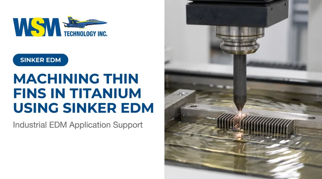
EDM eliminates these failure modes, but titanium work introduces a process safety requirement worth noting: hydrocarbon dielectric fluids present a flash-fire risk if fluid level drops below the workpiece during cutting. Shops running titanium on sinker EDM machines with oil-based dielectrics must maintain proper fluid level controls. This is a real operational hazard, not a theoretical one.
Wire EDM systems using deionized water as dielectric eliminate this risk entirely, which is one reason wire EDM is often preferred for titanium through-profiles.
Hardened Tool Steels Above 50 HRC
Hardened steels used in aerospace tooling, fixtures, and structural components above 50 HRC terminate carbide tool life quickly in conventional milling. EDM treats hardness as irrelevant because the spark erosion process has no mechanical component that wears in response to workpiece hardness. Studies on D2 steel EDM confirm the process remains viable at hardness levels that would make conventional tooling impractical.
Practical implications for aerospace work include:
- Finish-hardened components can be EDM'd after heat treatment, eliminating distortion from post-machining hardening cycles
- Complex cavities in H13 and D2 tooling steels are routinely held to ±0.0002" without concern for workpiece hardness
- No tool pressure means thin walls and fragile features in hardened steel remain stable during cutting
Electrode Material: A Decision That Affects Aerospace Outcomes
Electrode selection for sinker EDM directly affects part accuracy:
| Electrode Material | Best Application | Key Characteristic |
|---|---|---|
| Graphite | Large cavities, aggressive roughing | Wear below 1% of depth of cut under high-amperage conditions |
| Copper | General-purpose sinker EDM | Higher wear than graphite in roughing |
| Copper-tungsten | Fine-detail features, hard/exotic alloys | Preferred for sharp corner reproduction and hard material sinker work |

For deep aerospace cavities (turbine blade cooling slots, fuel system pocket features) graphite's low wear ratio reduces dimensional error accumulation over the depth of cut.
Tolerance, Surface Finish, and the Recast Layer
Aerospace EDM output has three technically consequential parameters: dimensional tolerance, surface finish (Ra), and recast layer depth. Specifying only dimensional accuracy is insufficient. All three require definition and verification on safety-critical parts.
Dimensional Tolerance in Aerospace Wire EDM
Under controlled conditions — stable dielectric, calibrated wire tension, thermally stabilized machine, correct skim-cut sequence — wire EDM achieves:
- ±0.001 mm (1 µm): Reported by Mitsubishi/MC Machinery for their MX Series
- ±0.003 µm: Reported by Sodick for precision wire EDM
- ±0.005 mm: Historical Mitsubishi FA Advance catalog figure; represents the broader production range under less-than-ideal conditions
These are machine capability figures under controlled lab or demonstration conditions. Production tolerance achievement depends on process discipline: dielectric maintenance, electrode inspection logs, skim-cut sequence execution, and fixturing stability across the full run.
Mitsubishi EDM systems, available through WSM Technology, incorporate dielectric temperature control synchronized with machine structure — a design feature that helps maintain consistent tolerances across long aerospace production runs where thermal drift is a real risk.
Surface Finish and Fatigue Life
EDM surface finish affects more than appearance. Rougher surfaces from aggressive roughing parameters increase fatigue crack initiation risk on cyclic-load components — turbine disks, landing gear brackets, structural fittings.
Multi-pass skim cutting progressively improves Ra:
- Roughing passes: 2.29–3.18 µm Ra (90–125 µin Ra)
- Precision skim passes: 0.32–0.40 µm Ra achievable on production wire EDM
- Ultra-precision conditions: below 0.20 µm Ra on specialized machines
Skim-cut sequences must be part of the process plan from the start, not added after dimensional issues appear.
Achieving tight Ra values is necessary but not sufficient. Beneath the surface finish, a separate structural concern forms during every EDM operation.
The Recast Layer: Structural Risk in Aerospace EDM
Every EDM surface produces a recast layer: a thin zone of rapidly re-solidified material formed when the discharge melts and re-deposits workpiece material before the dielectric can flush it away.
A 2025 peer-reviewed study on GH3536 superalloy found that at a 50 µs pulse width, the recast layer averaged ~14 µm thick and exhibited:
- Microcracking and pores
- Residual tensile stress
- 20.4% higher hardness than the base material (4.77 GPa vs. 3.96 GPa)
- Fatigue cracks originating from recast microcracks and pores (34.25% and 15.07% of crack-source shares, respectively)
- Early fatigue failure before 5×10⁷ cycles in high-stress defect regions

For aerospace safety-critical components, the recast layer is a structural risk. Treating it as a surface finish specification is a process error. Standard removal methods include:
- Subsequent grinding or honing
- Electrochemical machining (ECM)
- Electropolishing (for certain geometry types)
Recast depth and removal requirements must be defined in the part's process documentation and verified at inspection. Assuming removal without documentation is not acceptable on safety-critical parts.
Wire EDM vs. Sinker EDM for Aerospace Components
Choosing between wire and sinker EDM comes down to part geometry — specifically, whether the feature is a through-profile or an enclosed cavity.
Wire EDM uses a continuously fed conductive wire to cut through-profiles and contoured shapes. It's the correct process for:
- Turbine blade and disk profiles (fir-tree root forms, airfoil contours)
- Structural brackets and cutouts
- Extrusion die profiles
- Any feature that is a through-cut with a defined 2D or 3D contour
Mitsubishi wire EDM systems, for example, are used at production scale for jet-engine turbine disk fir-tree patterns in nickel-based superalloys and Waspaloy disks — a demanding application that requires sub-micron repeatability across dozens of identical slots.
Sinker EDM uses a shaped electrode to create cavities, pockets, and blind features. It's required for:
- Enclosed cavities in turbine components
- Deep pockets that don't exit the workpiece
- Complex 3D negative geometry
- Features that require a specific shaped cavity profile
Aerospace components frequently require both processes in sequence: wire EDM for external profiles, sinker EDM for internal cavity features.
Process Trade-offs That Affect Lead Time and Cost
| Factor | Wire EDM | Sinker EDM |
|---|---|---|
| Electrode management | Wire is continuously fed; no wear compensation needed | Shaped electrode requires preparation and wear compensation programming |
| Verification | Easier — CMM on through-profile | More complex — cavity geometry verification |
| Setup complexity | Lower | Higher (electrode prep adds lead time) |
| Best for | Through-features, contours, slots | Cavities, pockets, shaped 3D negatives |

WSM Technology carries wire EDM systems including the Mitsubishi MV1200S — equipped with linear shaft motors and linear glass scales — alongside sinker EDM options from Mitsubishi and OPS Ingersoll. Both process types are available for evaluation at WSM's demonstration center in Rootstown, Ohio, where engineers can run test cuts on actual aerospace geometries before committing to production parameters.
Real-World Aerospace EDM Production: What Closes the Gap Between Capability and Compliance
The gap between published machine capability and actual shop-floor aerospace tolerance achievement comes from four sources:
- Dielectric management — contamination, temperature drift, and inadequate flow rate all degrade tolerance repeatability
- Electrode condition and wear compensation — uncorrected electrode wear in sinker EDM accumulates as dimensional error
- Workpiece fixturing — thermal and mechanical instability during long EDM cycles shifts datum references
- CNC program quality — incorrect skim-cut sequences and improper corner radius compensation produce non-conforming parts regardless of machine capability
Compliance Is Part of the Process
Aerospace production EDM must be documented within a quality management system — typically AS9100 Rev D. SAE AS7116/3A covers Nadcap EDM accreditation for wire, sinker, and fast-hole EDM processes. The traceability chain includes:
- Process parameter records for each production run
- Electrode inspection logs
- First-article inspection (FAI) documentation per AS9102C
- Dielectric maintenance records
Dimensional results that can't be traced back to documented process parameters will not pass an aerospace customer audit. Getting that traceability right is inseparable from choosing the right process in the first place.
Don't Misapply EDM to the Wrong Operations
EDM cannot match milling speeds for bulk material removal. Applying it as a roughing process for large aerospace structural sections inflates cycle time without gaining any precision benefit. The correct application model:
- Conventional machining rough-shapes the part
- EDM handles precision features, difficult materials, or geometrically inaccessible features that conventional tooling cannot reach
- Post-EDM finishing (deburring, surface verification) closes the loop before inspection

WSM Technology's application engineering team offers process consultation, test cuts, and time studies to help aerospace shops pinpoint where EDM genuinely adds value. That upfront analysis prevents the common mistake of over-applying EDM to operations where milling is faster and equally accurate.
Frequently Asked Questions
What tolerances can wire EDM achieve for aerospace-grade components?
Under controlled conditions — stable dielectric, calibrated machine, multi-pass skim cutting — wire EDM achieves tolerances in the ±0.001 mm to ±0.005 mm range. Sustaining these tolerances in production requires process discipline (documented parameters, electrode inspection, dielectric management), not just machine capability.
Is wire EDM or sinker EDM better for aerospace manufacturing?
The right choice depends on the feature. Wire EDM handles through-profiles, contoured shapes, and high-aspect-ratio cuts; sinker EDM is required for enclosed cavities, deep pockets, and complex 3D negative features. Many aerospace components require both processes in sequence.
What materials can EDM machine that conventional cutting tools struggle with?
EDM handles nickel-based superalloys (Inconel 718, Waspaloy), titanium alloys (Ti-6Al-4V), hardened tool steels above 50 HRC, and refractory metals effectively. Because EDM is non-contact and hardness-independent, it succeeds where conventional tools fail from work-hardening, thermal damage, or tool adhesion.
What is the recast layer and how does it affect aerospace components?
The recast layer is a rapidly re-solidified surface zone formed during EDM discharge, containing altered microstructure, residual tensile stress, and micro-cracks. On fatigue-critical aerospace parts, it's a fracture risk. Removal via grinding, honing, or electrochemical machining is required, with depth specified and verified in process documentation.
Can EDM be used to repair or rework existing aerospace components?
Sinker EDM can rework cavities, restore worn features, or remove broken tooling from aerospace parts. Any rework must be performed under an approved engineering disposition with full traceability — standard EDM rework practices don't override the part's specific quality requirements.
How does EDM compare to conventional machining for titanium aerospace parts?
Conventional machining of titanium risks tool adhesion, built-up edge, and heat-induced microstructural damage. EDM avoids cutting forces entirely, though oil-based sinker EDM setups require careful dielectric fluid management to prevent flash-fire risk. For complex, tight-tolerance titanium features, EDM is often the preferred or only viable option.