Introduction
Walk up to a Mitsubishi wire EDM machine for the first time, and the control panel can feel like the cockpit of an airplane.
Multiple screens, layered menus, threading sequences, offset tables — it's a lot to absorb. That's especially true for operators moving over from manual machining or jumping from an older control generation to a newer one.
This friction is real. Mold and die shops, aerospace suppliers, medical manufacturers, and automotive plants all lean on the same control interface daily, and the learning curve shows up fastest in setup errors, not machine breakdowns.
This guide walks through the Mitsubishi wire EDM control screen-by-screen and step-by-step, built for actual shop-floor conditions rather than a polished factory demo.
Whether you're running an MV, MP, or FA series machine, the goal is the same: fewer wasted cycles, fewer scrapped parts, and more confidence at the panel.
Key Takeaways
- The control panel is organized into five dedicated menus: File, Setup, Machining Support, Monitor, and Maintenance
- Most control-related downtime traces back to skipped verification steps, not actual machine faults
- Wire offset and corner compensation (CM/CM3 control) directly protect tolerance and part accuracy
- Hands-on training at a demo center builds control confidence far faster than reading a manual alone
Understanding the Mitsubishi Wire EDM Control Panel
Mitsubishi has used different control naming across generations, so it helps to know which one you're standing in front of. Older FA Advance, MV, and MP machines run on W31 ADVANCE control units (some FA Advance models paired this with an M700-CNC).
Newer named MV models, like the MV1200-S Advance Type and MV2400-R Advance Plus, carry the M800 series CNC control with a larger 19-inch touchscreen.
Screen Zones You'll Actually Use
Regardless of generation, the control's menu structure stays consistent across five zones:
- File: loading, saving, and managing NC programs
- Setup: workpiece datum, wire offset, and threading configuration
- Machining Support: condition search and cutting parameter selection
- Monitor: live cutting status, feed rate, and program progress
- Maintenance: consumable checks and alarm history

Both older and newer controls use touch-panel navigation with a keyboard and mouse. This isn't a strict "old keypad versus new touchscreen" split: even the 2010-era FA Advance control had a 15-inch touch panel.
The real difference between generations is screen size and gesture support, not whether touch exists at all.
Offset and Corner Compensation
The Setup screen holds the Wire offset field, which compensates for wire radius and discharge gap to hold your programmed geometry. Mitsubishi's documented input range runs to ±99999.999 mm across up to 900 offset numbers, giving shops plenty of room to store offsets per job or per wire type (Mitsubishi MV series catalog).
For tight corners, CM control (Corner Master) on FA machines and CM3 control on MV/MP models reduce wire lag at small inside and outside corners, a common trouble spot on intricate mold cavities.
Alarm and Diagnostic Screens
The Maintenance menu houses the Alarm display, which flags issues like wire breakage or fluid faults. Shops running MC Machinery's remote360 monitoring can also see machine state (cutting, idle, or in alarm) plus working voltage and water quality remotely (MC Machinery remote monitoring).
New operators often skip straight to cycle start without checking these screens first. That shortcut is where most avoidable setup errors begin.
What You Need Before Operating the Control
Before you touch a single screen, confirm these three things are in place:
- Machine powered up, axes homed, and dielectric fluid primed. The control won't execute inputs correctly if the machine hasn't returned to its reference position.
- A verified NC program loaded, whether from CAM output or manual data input. Without valid geometry, the control has nothing accurate to cut.
- Appropriate supervision for first-time operators. New users benefit from structured, hands-on practice before touching a production part.
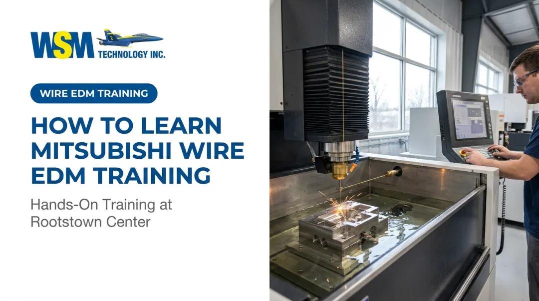
That third point matters more than most training checklists admit. Reading a manual teaches you where the buttons are, but it doesn't teach you what a threading fault feels like in real time. WSM Technology's demonstration center in Rootstown, Ohio lets operators practice screen navigation and auto-threading on a live MV1200-S before running a customer job. That kind of repetition shortens the learning curve considerably.
How to Use the Mitsubishi Wire EDM Control (Step-by-Step)
The control follows a defined screen sequence for a reason. Skip a step, like not verifying home position or offset values, and you're looking at scrapped parts or wire breaks, not a minor inconvenience.
Powering On and Homing the Machine
Startup runs through power checks, safety interlock confirmation, and a return to machine reference (home) position. This home-return step establishes coordinate accuracy for everything that follows.
Common mistake: bypassing home return to save a few minutes. That shortcut throws off positioning for the entire job, and it's rarely obvious until the part comes out wrong.
Loading and Verifying the NC Program
Programs load through the File menu via USB, network connection, or manual entry. Before cutting anything, run the graphic simulation to confirm the toolpath matches your intent.
This simulation check is your green light. Skipping it means your first real confirmation of correct geometry happens mid-cut, too late to matter.
Setting Up Workpiece Datum and Auto-Threading the Wire
From the Setup screen, establish the workpiece origin, then activate automatic threading. Mitsubishi's AT2 high-speed auto-threader typically threads in around 10 seconds, with annealing systems producing a straighter wire end for more reliable insertion.
Confirm threading has completed successfully — through whatever status indication your specific control revision provides — before advancing to cutting. Check your machine's operator manual for the exact confirmation display, since this varies by control generation.
Configuring Cutting Conditions on the Parameter Screen
Under Machining Support, use the condition search function to pull up settings suited to your material and thickness. Mitsubishi's ME-pack bundles offset, machining speed, and adaptive-control settings together, while PM control (Power Master) automatically adjusts rough-machining conditions toward optimum performance. TS Master manages wire tension separately to reduce fluctuation during the cut.
Correct setup here ties directly to surface finish consistency and cutting speed: get it wrong, and you'll see it in both.
Running and Monitoring the Cut
Watch the Monitor screen for feed rate, voltage/current readings, and cycle progress. Early warning signs worth catching:
- Wire-break alarms appearing repeatedly at the same location
- Arcing or unstable feed rate patterns
- Cycle progress stalling without an obvious cause
Catching these early, rather than walking away and hoping for the best, saves both wire and workpiece material.
Completing the Job and Shutting Down Properly
Confirm program completion on-screen, retract the wire, and power down through the proper sequence rather than just hitting the main switch. A rushed shutdown skips fluid drainage and filter checks, which sets up tank contamination or startup errors on the next job.

Best Practices for Operating the Control Effectively
A few habits separate shops with consistent results from shops constantly troubleshooting:
- Run a pre-cut screen-check routine every time (home position, program verification, offset check), regardless of how experienced the operator is
- Watch dielectric fluid cleanliness and filter condition closely; dirty fluid skews sensor readings and directly affects cutting consistency
- Back up programs and parameter sets regularly to protect against data loss and rework
- Keep OEM-supported consumables stocked, including wire, filters, and resin tanks, to avoid downtime from worn components
WSM Technology supplies these consumables through its affiliated CPG Department and Encore Group across Northern Ohio, Western Pennsylvania, and West Virginia. This keeps shops from scrambling when a filter or resin tank needs replacing mid-job.
Conclusion
Mastering the Mitsubishi wire EDM control means following the same verification sequence every single time. Check home position, verify the program, and confirm offsets, no matter how many times you've run the machine before.
That discipline protects precision and keeps scrap costs down. If you're building that habit on a new control generation, hands-on training at WSM Technology's demo center and direct technical support will get you there faster than any manual.
Frequently Asked Questions
What is the wire cut EDM machine process?
According to MC Machinery, wire EDM removes material from an electrically conductive workpiece using controlled electrical discharges between the workpiece and a continuously moving wire electrode. The control system guides and monitors this process along a programmed path.
What type of control does a Mitsubishi wire EDM machine use?
Older FA Advance, MV, and MP machines use W31 ADVANCE control units, sometimes paired with M700-CNC. Newer named MV models run on the M800 series CNC control with a larger touchscreen interface.
How does automatic wire threading work on the control?
Operators activate the auto-threading function from the Setup screen, and systems like Mitsubishi's AT2 threader handle insertion in roughly 10 seconds. Check your specific operator manual for the exact completion confirmation your control displays.
What causes wire breakage during a cut, and how does the control help diagnose it?
Wire breakage often stems from tension inconsistency, flushing issues, or incorrect machining conditions. The Alarm display and Maintenance check functions flag the fault, while remote360 monitoring can log breakage events for review.
Can operators get hands-on training on Mitsubishi wire EDM controls?
Yes. Dealer-led demo centers, like the one WSM Technology operates in Rootstown, Ohio, let operators practice screen navigation and threading on live equipment before running production parts.
How often should control parameters be checked or updated?
Verify parameters at every new job setup, and review them again whenever material type, thickness, or wire specification changes. Skipping this step is a common source of avoidable finish and speed inconsistencies.