Key Takeaways
- Aerospace grinding targets tolerances in the tenths of thousandths — and surface integrity requirements that go well beyond Ra surface finish.
- Low-conductivity alloys like Inconel 718 and Ti-6Al-4V trap heat at the grinding zone, making thermal management the primary challenge.
- Grinding burn creates tensile residual stress and microstructural damage that passes visual inspection but fails in service; detection requires nital etch or Barkhausen noise testing.
- AMS specifications, NADCAP accreditation, and AS9100 documentation requirements govern aerospace grinding — scope varies by customer and part.
- Grinding appears across the aerospace manufacturing lifecycle: production finishing, MRO restoration, and post-additive-manufacturing refinement.
What Is Aerospace Component Grinding?
Aerospace component grinding is the controlled removal of material from flight-critical parts using bound abrasive wheels to achieve precise geometry, surface finish, and subsurface material condition. Tolerances commonly fall in the tenths-of-thousandths range — tighter than conventional milling or turning can reliably deliver on finish-ground features.
The process is designed to accomplish three things simultaneously:
- Achieve final dimensional accuracy on parts that have already been rough-machined
- Prepare surfaces for coatings, sealing, or assembly interfaces
- Preserve subsurface material properties in heat-sensitive alloys where thermal damage is invisible but structurally consequential
Aerospace grinding diverges from general industrial grinding in three specific ways: the materials being processed, the surface integrity requirements beneath the visible surface, and the documentation stack that accompanies every operation.
A shop grinding 4140 steel to ±0.001" and a shop grinding Inconel 718 turbine disc slots to bearing fit are running fundamentally different processes, even if both call it "grinding."
Why Grinding Is Critical in Aerospace Manufacturing
The Last Line of Process Control
Grinding is frequently the final operation before inspection and delivery. That position in the workflow makes it the last opportunity to bring geometry within tolerance and surface finish within specification — and the last point where undetected process errors have no downstream correction.
Aerospace demands something most industries don't: documented surface integrity, not just dimensional accuracy. Aerospace quality systems require traceability to material lot and wheel lot. Rework is often not an option because aerospace parts can't be salvaged once subsurface damage is introduced.
What Goes Wrong Without Process Discipline
The consequences of inadequate aerospace grinding are severe. NTSB investigations of high-strength steel landing gear components have linked fatigue fractures directly to excessive grinding, grinding burns, and heat-damaged regions — all originating at the grinding contact zone, all invisible on the surface.
Three failure mechanisms are typically involved:
- Grinding burn (thermally-induced damage at the wheel-workpiece interface) converts compressive residual stress into tensile residual stress
- Stress reversal accelerates fatigue crack initiation even when dimensions check out perfectly
- Subsurface damage passes every visual inspection yet initiates cracking in service

The part looks correct. The part measures correctly. It fails anyway.
Shops that apply parameters developed for standard steels directly to nickel superalloys or titanium make this worse. The failure mode is thermal, not dimensional. Reducing feed rate alone, without adjusting wheel selection, dressing, and coolant delivery, can actually increase heat input by extending dwell time in the contact zone.
The Regulatory Reality
Aerospace grinding compliance comes from three directions at once:
- AMS specifications define material property requirements and inspection standards (AMS2649E covers etch inspection of high-strength steel parts at 180,000 psi and above to detect overheating from abusive grinding)
- NADCAP governs specific processes at many prime contractors — nital etch and chemical processing fall under AS7108/2; conventional machining including grinding is addressed separately under AC7126
- Operational necessity forces process discipline regardless of certification status, because the physics of machining superalloys doesn't change based on paperwork
How Aerospace Component Grinding Works
The Process Sequence
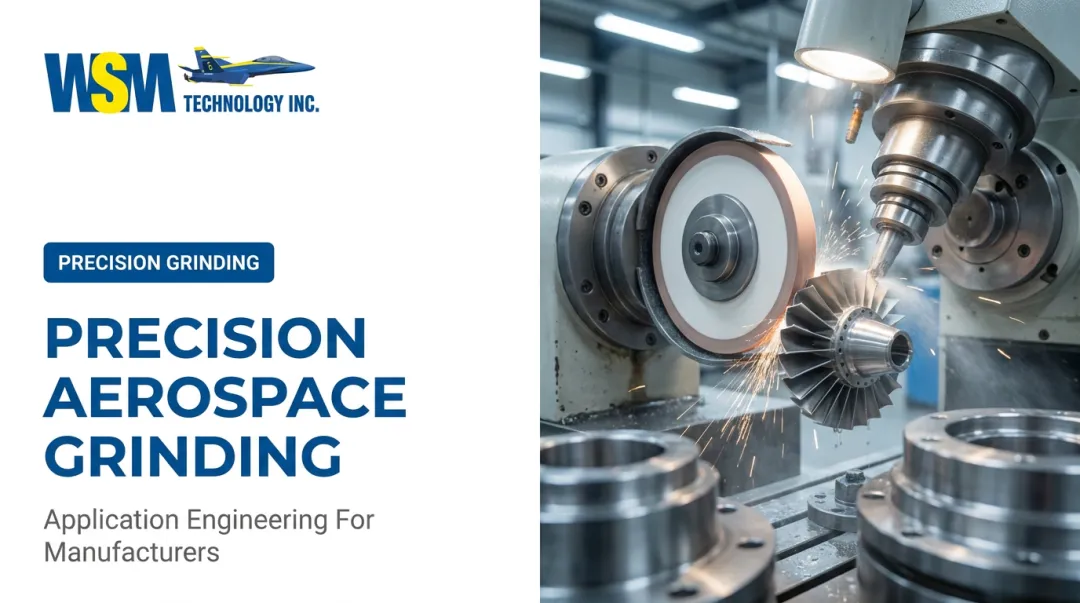
A bound abrasive wheel contacts the workpiece at a controlled depth of cut and feed rate, removing material through micro-cutting and abrasion. Coolant delivers thermal management at the contact zone. The sequence — setup, dressing, rough grind, finish grind, inspection — is controlled to preserve both geometry and subsurface material condition.
Every variable in the process interacts with the others:
- Workpiece material and its thermal properties
- Abrasive wheel specification (type, grit, bond, grade)
- Dressing tool and parameters (frequency, lead, depth)
- Coolant type, concentration, and delivery pressure
- Machine rigidity and thermal stability
Selecting any one of these in isolation from the others is how shops get into trouble.
The Thermal Problem in Aerospace Alloys
The reason aerospace grinding is harder than standard grinding comes down to thermal conductivity. Ti-6Al-4V conducts heat at 6.7 W/m·K. AISI 52100 bearing steel conducts at 46.6 W/m·K — nearly seven times better. Inconel 718 sits at comparable low-conductivity levels for a nickel superalloy.
When a low-conductivity material enters the grinding zone, heat accumulates at the surface faster than coolant can extract it. That's the root cause of grinding burn, re-tempering, and alpha-case formation in titanium — an oxygen-enriched, brittle surface layer that forms above roughly 480°C and reduces fracture toughness at the part surface.
Rough Grinding vs. Finish Grinding
The two grinding stages serve fundamentally different objectives:
| Rough Grinding | Finish Grinding | |
|---|---|---|
| Primary Goal | Material removal rate | Surface integrity and tolerance |
| Depth of Cut | Aggressive | Light passes |
| Wheel Grit | Coarser | Finer |
| Heat Risk | Lower priority — but subsurface damage here can't always be removed later | Critical — coolant delivery and feed rate are optimized to minimize heat input |

The key point at the rough stage: wheel selection and depth of cut still matter. Subsurface damage introduced during rough grinding is not always recoverable in finish passes.
Post-Grind Inspection
Post-grind inspection in aerospace is not optional and is not limited to dimensional measurement. It typically includes:
- Surface finish measurement (Ra)
- Nital etch inspection to detect grinding burn — acid discoloration indicates re-tempering or microstructural alteration
- Microhardness testing or residual stress measurement where specified
One important limitation: nital etch reveals burn only where metallurgical transformation has occurred. It does not detect residual stress in the absence of microstructural change. For high-strength steel parts, ARP4462C Barkhausen noise inspection provides a complementary method specifically for grinding burn detection. Results must be documented on the part traveler.
Inspection findings don't exist in isolation either. High-speed milling typically rough-machines near-net-shape features before grinding achieves final form — which means surface integrity issues flagged at inspection often trace back to decisions made earlier in the process sequence, not just at the grinder.
Where Aerospace Grinding Is Applied
Different component families call for different grinding types. The table below maps the main applications:
| Component Family | Grinding Type | Application Context |
|---|---|---|
| Turbine blades, vanes, shrouds | Profile / creep-feed | Airfoil geometry and tip profiles |
| Turbine discs and shafts | Cylindrical OD/ID | Bearing fits and seal diameters |
| Landing gear components | Cylindrical / surface | Post-HVOF coating finishing |
| Engine seals | Surface / cylindrical | Flatness and height tolerances |
| Aircraft brake rotors | Rotary surface | MRO resurfacing for wear and scoring |
Where Grinding Fits in the Component Lifecycle
Grinding appears at three distinct stages:
- Production — as a final finishing step after milling, turning, or forging
- MRO — as a resurfacing operation to restore worn or damaged components to airworthy condition
- Post-AM finishing — as an increasingly common step for additively manufactured aerospace parts requiring dimensional refinement and surface integrity restoration
Each MRO trigger is condition-based. Common causes include:
- Brake rotors: scoring, uneven wear, and surface deformation from heat and friction during landing cycles
- Landing gear: surface damage at bearing and seal interfaces
- Engine seals: loss of flatness tolerances accumulated over service life

For aerospace suppliers and MRO shops in Northern Ohio, Western Pennsylvania, and West Virginia, WSM Technology's grinding portfolio covers the machine types directly applicable to these component families. That includes Danobat cylindrical, OD/ID, vertical, and centerless grinders, Overbeck external/internal grinders, and the Ziersch Z24 surface grinder.
Key Factors That Affect Aerospace Grinding Outcomes
Five variables consistently determine whether an aerospace grinding operation produces acceptable parts or rejects: material properties, wheel selection, dressing parameters, coolant strategy, and documentation. Getting any one of them wrong can cascade into scrap, rework, or a part that fails qualification — even if it looks correct.
Material Properties
Thermal conductivity is the primary variable that determines how aggressively a wheel can engage the workpiece before burn occurs. The gap between titanium (6.7 W/m·K) and bearing steel (46.6 W/m·K) is large enough to require entirely different parameter sets — what is safe on steel will cause thermal damage on titanium.
Wheel Selection
Wheel selection is a system decision, not a commodity choice:
- CBN wheels — preferred for nickel superalloys; maintain sharp cutting edges and generate less heat per unit of material removed
- Diamond wheels — used for ceramics and ceramic matrix composites
- SG ceramic alumina wheels — effective on select titanium and stainless alloys; require careful grade and bond selection
The wrong wheel grade for the material and application accelerates thermal damage and reject rates.
Dressing Parameters
A glazed or poorly dressed wheel generates far more heat than a sharp, open wheel. In aerospace, dressing frequency and lead are process parameters that must be controlled and documented with the same rigor as depth of cut — and they are among the most commonly overlooked variables in shops moving from standard to aerospace work.
Coolant Strategy
High-pressure, high-volume delivery is required to penetrate the grinding zone on difficult materials. Key parameters include:
- Coolant pressure: 175 psi at 55 gal/min for demanding applications (per Norton documentation)
- Scrubber nozzles: 500–1,000 psi for effective chip removal
- Concentration control: Must be maintained at specified levels throughout the run
- Chemical compatibility: For composite materials, verify compatibility with both the matrix and the process specification before selecting coolant

Documentation and Traceability
Traceability is a process factor, not just a paperwork requirement. A part can be dimensionally and visually acceptable and still be disqualified from delivery if any single record is missing. Required documentation typically includes:
- Wheel lot number
- Dressing parameters
- Coolant batch records
- Machine ID and operator ID
- Calibration records
Common Misconceptions About Aerospace Grinding
Ra Alone Doesn't Confirm Surface Integrity
Ra measures surface profile amplitude. It says nothing about residual stress, microhardness, or thermal damage in the subsurface layer. A part can have a perfect Ra reading and carry grinding burn that will initiate fatigue cracking in service.
Surface integrity encompasses roughness, phase structure, residual stress, and corrosion properties. Ra alone addresses only one of those.
Slowing Feed Rate Doesn't Fix a Thermal Problem
This logic fails because the core problem in aerospace grinding is thermal, not dimensional. Without wheel, coolant, and dressing adjustments optimized for the specific alloy, slowing feed rate can extend dwell time in the contact zone and worsen heat input. That's the opposite of the intended effect.
NADCAP Scope Is Narrower Than Most Assume
NADCAP governs specific processes. Nital etch and chemical processing fall under AS7108/2. Grinding falls under a different accreditation scope.
Some aerospace prime contractors require NADCAP for grinding operations; others don't. The actual requirement depends on the customer, the prime, and the specific part. Verify accreditation requirements directly with the customer before assuming certification is either required or sufficient.
Frequently Asked Questions
What types of grinding are used for aerospace components?
The main types are cylindrical (OD/ID), surface, centerless, and profile grinding. Turbine blades and vanes use profile grinding for airfoil geometry; turbine discs and shafts use cylindrical OD grinding for bearing fits; landing gear and engine seals use surface and cylindrical grinding; brake rotors use rotary surface grinding in MRO.
What materials are most commonly ground in aerospace manufacturing?
Nickel-based superalloys (Inconel), titanium alloys, case-hardened steels, ceramic matrix composites, and carbon fiber reinforced polymers are the primary material classes. Each requires a distinct grinding strategy due to significant differences in thermal conductivity, hardness, and sensitivity to surface damage.
What is grinding burn and how is it detected in aerospace parts?
Grinding burn is thermally-induced surface and subsurface damage from excessive heat at the wheel-workpiece interface. Detection methods include nital etch inspection (acid discoloration indicates re-tempering) and Barkhausen noise analysis per ARP4462C. Note that nital etch alone will not detect residual stress unless microstructural change is also present.
What certifications or standards apply to aerospace grinding operations?
Key standards include AMS specifications (AMS2649E covers etch inspection of high-strength steel), NADCAP accreditation for specific processes (nital etch under AS7108/2; grinding under a separate machining scope), and AS9100 for the quality management system. Exact requirements vary by customer and process.
How does aerospace grinding differ from general precision grinding?
The key differences are material difficulty, surface integrity requirements that extend beyond Ra to include residual stress and microhardness, and documentation traceability demands that far exceed typical job shop standards. The consequences of process errors — subsurface damage, fatigue crack initiation — are also categorically more severe.
Can grinding be used on additively manufactured aerospace parts?
Yes. Grinding is increasingly used as a post-process step for AM aerospace components to achieve final dimensional accuracy and surface integrity. Parameter selection requires care: additive parts can carry internal porosity and residual stresses that respond differently to grinding than wrought material.