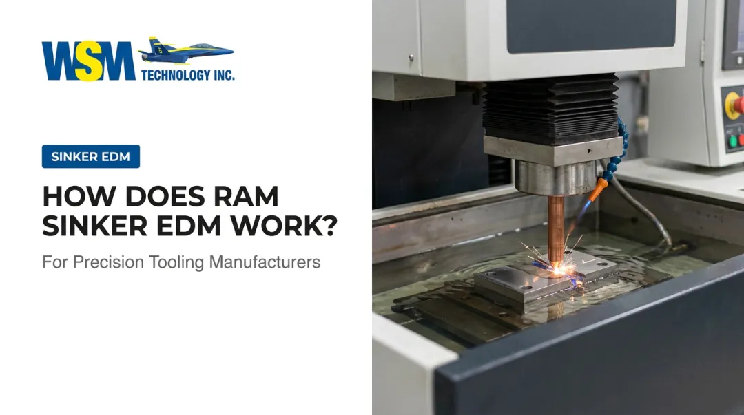
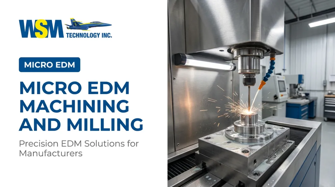
Sinker EDM solves this by removing material through spark erosion without any physical contact. No cutting force means no deflection. But results vary considerably depending on electrode design, parameter discipline, and dielectric management. Get those wrong in titanium, and you trade tool chatter for cracked fin walls and thick recast layers.
This article covers the full process: how to set it up, which parameters matter most, what goes wrong, and when to use a different method entirely.
Key Takeaways
- Sinker EDM exerts zero cutting force, making it the right method when fin walls are too thin to survive milling without deflecting
- Copper electrodes outperform graphite for titanium — lower tool wear ratio and better dimensional retention over long cycles
- Progressive finishing passes are not optional; each pass reduces recast layer thickness toward acceptable levels
- Use hydrocarbon oil dielectric — contaminated fluid is a leading cause of arc damage on fin walls mid-cycle
- Validate all parameters on a matching scrap piece before running a production blank
How to Machine Thin Fins in Titanium Using Sinker EDM
Step 1: Design and Fabricate the Electrode
Design the electrode as the inverse of the fin geometry, with overburn (spark gap) compensation applied to all surfaces.
Overburn values in titanium differ from steel — the lower electrical conductivity of Ti-6Al-4V (roughly 0.97% IACS compared to 6.95% IACS for AISI 4340) affects spark behavior and gap size. Do not assume steel-based compensation values will transfer; validate them empirically or pull them from your machine manufacturer's application data.
Choose copper over graphite. Published Ti-6Al-4V die-sinking EDM data shows:
| Electrode | MRR (mm³/min) | Tool Wear Ratio (mm³/mm³) |
|---|---|---|
| Copper | 1.484–21.235 | 0.022–0.511 |
| Graphite | 0.696–6.483 | 1.255–3.376 |

Copper's roughly 5–150x lower wear ratio matters most in the thin rib sections of the electrode — those ribs define the fin gaps, and uneven erosion produces tapered fins. Graphite also carries higher risk of carbon deposits on the thermally sensitive titanium surface.
Machine those rib sections with enough rigidity to resist deflection during the EDM cycle.
Step 2: Fixture the Workpiece and Establish Electrical Ground
Before starting, work through this setup checklist:
- Clamp with zero movement tolerance — EDM cycles for thin fins run long, and titanium's springback can shift part position incrementally enough to affect wall consistency across multiple fin cavities
- Establish a direct, low-resistance ground from the workpiece to the machine table; any weakness further degrades spark efficiency on an already low-conductivity material, and erratic sparking damages fin walls in ways that are difficult to diagnose
- Use hydrocarbon EDM oil as dielectric — published Ti-6Al-4V die-sinking studies used synthetic hydrocarbon kerosene and dedicated EDM oil; water on burning titanium can generate hydrogen gas, which is why oil is standard practice for sinker EDM of this material
- Verify the tank and filtration system are clean before loading a titanium part; residual debris from prior jobs contaminates the dielectric from the first spark
Step 3: Program and Execute the Roughing Operation
Set low peak current and short pulse-on time for roughing. Titanium's low thermal conductivity means heat builds in the cut zone faster than it can escape. High discharge energy causes thermal stress in thin fin walls — the walls cannot absorb it, and cracking or distortion follows.
Research on Ti6Al4V die-sinking EDM confirms that lower energy settings reduce recast layer thickness. Start conservative and work up only if needed.
Three things to activate and monitor during roughing:
- Orbital (planetary) motion — creates side-to-side electrode movement that opens the flushing gap and carries eroded titanium particles out of the narrow fin cavity; without it, debris accumulates and secondary arcing follows
- Flushing nozzle position — direct flow into fin cavities, not just the general tank area
- Spark gap stability indicators — if the machine shows frequent short-circuits or servo hunting, reduce energy immediately; titanium cannot absorb prolonged instability without surface damage
Step 4: Execute Progressive Finishing Passes to Final Geometry
Reduce discharge energy with each finishing pass: lower peak current and shorter pulse duration than the previous pass, every time. This progressive step-down is the mechanism that drives recast layer thickness toward acceptable levels.
A 2021 study on high-power Ti-6Al-4V ELI EDM found white layer (recast) thickness ranging from 16.00 to 67.14 µm, with HAZ extending 32.07 to 132.00 µm. A separate study found EDM reduced Ti-6Al-4V fatigue strength by 15–30% compared to finely milled specimens. Target a recast layer under 20 µm for fatigue-critical fin applications; anything above 50 µm requires additional post-processing such as electrochemical or abrasive flow machining to recover surface integrity.

After the final pass:
- Measure fin wall thickness with CMM or contact gauge
- Verify surface roughness with a profilometer
- Do not remove the part from the fixture until it meets specification
When Is Sinker EDM the Right Method for Thin Fins in Titanium?
Sinker EDM is the right choice when the geometry or material behavior puts milling and wire EDM out of reach:
- Fins are too thin for milling — lateral cutting forces deflect or crack the walls before the tool completes the pass. MC Machinery confirms sinker EDM exerts no physical force, enabling thin walls and high-aspect-ratio features milling cannot hold
- Fins are blind features — enclosed at the bottom, which wire EDM cannot produce and milling cannot reach cleanly in deep, narrow cavities
- Fins have undercuts or complex 3D profiles — shaped electrodes can produce geometry that neither wire EDM nor milling can replicate
Wire EDM or milling outperforms sinker EDM when:
- Fins are simple through-slots with no blind floors — wire EDM is faster, cheaper, and produces lower recast layers in that scenario. GF AgieCharmilles data shows Ti-6Al-4V WEDM recast under 6 µm after roughing, effectively eliminated after four finishing cuts
- Production volumes are very high — electrode fabrication time and wear costs accumulate; at scale, the economics shift toward wire EDM or milling if geometry permits
What You Need Before Machining Thin Fins in Titanium with Sinker EDM
Equipment and Machine Requirements
The sinker EDM machine must support orbital/planetary motion control and have a modern generator capable of low-energy, short pulse-duration settings. Older capacitor-style generators cannot be controlled finely enough for thin-wall titanium — discharge energy steps are too coarse.
Mitsubishi sinker EDM machines available through WSM Technology are built for precision die-sinking in demanding materials, including aerospace titanium work.
Materials and Conditions
Before starting:
- Copper electrode stock, sized and machined to the fin geometry with orbital motion paths programmed
- Clean hydrocarbon EDM oil with a functioning filtration system — no carryover debris from prior jobs
- All four finishing passes pre-programmed with decreasing energy settings before the first workpiece is mounted
Skill and Process Readiness
Having the right materials in place only gets you so far — the operator needs to match them.
The operator must be able to read spark gap stability indicators and know when to intervene rather than let an unstable cycle run. A test cut on a scrap block of the same titanium alloy grade as the production part is mandatory — it is where overburn values, orbital radius, and finishing pass sequences get validated. WSM Technology's demonstration center in Rootstown, Ohio offers test cut services for exactly this kind of pre-production process validation.
Key Parameters That Affect Thin Fin Quality
Four variables drive outcomes in thin-fin titanium sinker EDM. Adjusting one without accounting for the others produces defects reliably.
Peak Current and Pulse-On Time Together, these set how much thermal energy each spark deposits — and in thin-fin work, excess heat is your primary source of recast and microcrack formation. Published experimental data on Ti-6Al-4V sinker EDM spans 25–200 µs pulse-on time at 25–65 A in one study and 500–1000 µs at 40–50 A in another. Neither range is a recipe for thin fins — both represent experimental envelopes. For thin walls, start at the low end of both and increase only if material removal rate is unacceptably slow.
Orbital Motion Radius and Speed Flushing efficiency depends on orbital motion — it determines whether fresh dielectric reaches the bottom of narrow fin gaps or debris accumulates there. Too little radius and debris bridges the gap, causing burn marks. Too large a radius and the electrode removes more material from fin walls than intended, causing dimensional drift. The correct value depends on fin gap width and must be confirmed during test cuts.
Dielectric Fluid Condition Titanium erodes into dense particles that settle faster than steel swarf, which means contamination builds up faster than most operators expect. Contaminated dielectric causes inconsistent surface finish, dimensional drift, and arc pitting. Increase tank cleaning and filter replacement frequency whenever switching to titanium — the interval appropriate for tool steel work is not sufficient.
Electrode Wear Compensation In thin-fin applications, narrow electrode rib sections wear faster than the body — and uncompensated wear shows up as shallow fin floors and tapered walls. To dial in compensation accurately:
- Measure the electrode before and after a representative cut cycle
- Input the actual wear rate into the machine's compensation algorithm
- Verify dimensional results against a test cut before running production

Skipping any of these steps transfers the error directly into your finished part.
Common Mistakes in Thin Fin Sinker EDM of Titanium
A few setup and process decisions consistently cause scrapped parts or failed inspections. These are the ones that come up most often:
- Aggressive roughing pushes high discharge energy into thin titanium fins, producing cracks or a recast layer too thick to remove in finishing passes — starting conservative costs less time overall
- Skipping finishing passes leaves recast layer thickness unchecked; each pass serves a distinct function, and removing any one of them produces surfaces that fail aerospace or medical inspection criteria
- Neglecting dielectric maintenance: titanium sludge accumulates faster than most operators expect, and dirty dielectric gets misdiagnosed as a parameter problem when arc damage appears mid-cycle
- Poor grounding creates erratic spark behavior — marginal electrical contact between the workpiece and machine table produces uneven material removal across fin surfaces
Troubleshooting Issues During Thin Fin Sinker EDM of Titanium
Most problems trace back to three root causes: thermal overload, flushing failure, or electrode geometry deviation.
Fin Wall Cracking or Surface Delamination
Peak current or pulse-on time is too high for the fin wall mass. Localized thermal stress builds at the recast boundary faster than the material can dissipate it — and the thin cross-section leaves almost no margin before cracking occurs.
Steps to resolve:
- Reduce peak current on roughing passes
- Verify pulse-off time is long enough for the cut zone to cool between sparks
- If cracks appear only after finishing passes, the roughing recast layer was too thick to be fully removed — rebuild the electrode and restart with lower roughing energy
Inconsistent Fin Wall Thickness or Dimensional Taper
Electrode wear compensation is off, or the orbital motion radius was set too large. Either condition causes progressive dimensional drift across the cut cycle.
Measure the electrode before and after a full cut cycle to quantify actual wear, then input that data into the machine's wear compensation setting. If fin walls are consistently undersize, verify the programmed orbital radius and reduce it.
Arc Damage (Burn Pits) on Fin Surfaces Mid-Cycle
Dielectric contaminated with accumulated titanium particles is the most common culprit. When flushing nozzles aren't directed into the fin gaps, debris bridges the spark gap and arc damage follows.
To recover from a burn pitting event:
- Stop the cycle and drain the tank completely
- Replace the dielectric, clean the tank, and inspect the filter
- Reposition nozzles to channel flow into fin cavities
If burn pitting recurs quickly after resuming, increase orbital motion and reduce material removal per pass.
Alternatives to Sinker EDM for Thin Fins in Titanium
Each alternative to sinker EDM has a defined process window. Understanding where those windows end helps clarify why sinker EDM is often the only viable path for thin, deep, or blind titanium fins.
| Method | Best When | Key Limitations |
|---|---|---|
| High-speed milling | Fins are thicker and wall height-to-thickness ratio stays within the process window; cycle time is a priority | Tool deflection limits fin wall thinness; titanium work-hardening accelerates tool wear; heat management is more complex |
| Wire EDM | Fins are through-features (no blind floors) and the wire can pass completely through | Cannot produce blind geometries; no undercut or 3D profiles; workpiece must accommodate wire threading |
| Laser machining | Very shallow fins (depth under a few millimeters) where throughput matters more than tight tolerances | Heat-affected zones in titanium are harder to control than EDM recast; depth capability is limited |

Micromilling of Ti-6Al-4V has achieved walls as thin as 25 µm at 20:1 aspect ratio in research conditions, which demonstrates real capability — but that is not a general production threshold. For most shops, milling becomes unreliable well before those extremes, and the appropriate cutoff depends on the specific part, fixture, tooling, and machine, not a universal rule.
Frequently Asked Questions
Can sinker EDM cut titanium?
Yes. Titanium's electrical conductivity is lower than steel, but it is sufficient for EDM. Modern sinker EDM generators with low-energy settings and hydrocarbon oil dielectric manage titanium's thermal sensitivity without the surface damage risks common in conventional machining.
What is sinker EDM used for?
Sinker EDM produces complex 3D cavities, blind features, deep thin ribs, and intricate mold or die geometries in hard or difficult-to-machine conductive materials. Common applications span aerospace, medical devices, automotive tooling, and mold making.
Is sinker EDM expensive?
Electrode fabrication, machine time, and dielectric consumables all factor into cost. For complex geometries in hard materials, sinker EDM is typically cost-justified when conventional machining would require multiple setups or produce scrap rates that exceed EDM overhead.
Which materials cannot be machined by sinker EDM?
EDM requires electrical conductivity. Non-conductive materials — ceramics, plastics, and most composites — cannot be machined by EDM. Among metals, titanium, hardened steel, carbide, and copper alloys are all suitable.
What electrode material is best for sinker EDM of titanium?
Copper is the preferred choice. Published Ti6Al4V ELI die-sinking data shows copper's tool wear ratio is far lower than graphite's — a critical factor for geometry retention in thin rib sections — while graphite carries a higher risk of surface deposits on titanium.
How thin can fins be machined with sinker EDM in titanium?
Achievable wall thickness depends on electrode rigidity, discharge energy control, and machine accuracy. Research-grade sinker EDM has produced features below 0.1 mm (0.004 in), but production minimums vary by setup — a test cut on your alloy and electrode design is the only reliable way to confirm the actual limit.