Horizontal machining centers (HMCs) have become the preferred platform for producing complex, multi-sided aerospace components at production scale. Their spindle orientation, pallet architecture, and automation compatibility address the specific challenges of aerospace alloys and geometries in ways that vertical machines simply can't match at volume.
This guide covers how HMCs work, why they outperform vertical alternatives for many aerospace applications, which components they produce best, and what to look for when selecting a machine and a regional support partner.
Key Takeaways
- HMCs use gravity to evacuate chips, protecting cutting zones when machining titanium and Inconel
- Twin-pallet systems eliminate load/unload downtime, enabling near-continuous spindle utilization
- Multi-face access in a single setup reduces cumulative fixturing errors on structural components
- Pallet automation can triple productive spindle hours — from 2,000 to over 6,000 per year (DMG MORI)
- Local application support and dealer infrastructure directly affect uptime and AS9100D compliance outcomes
What Is a Horizontal Machining Center?
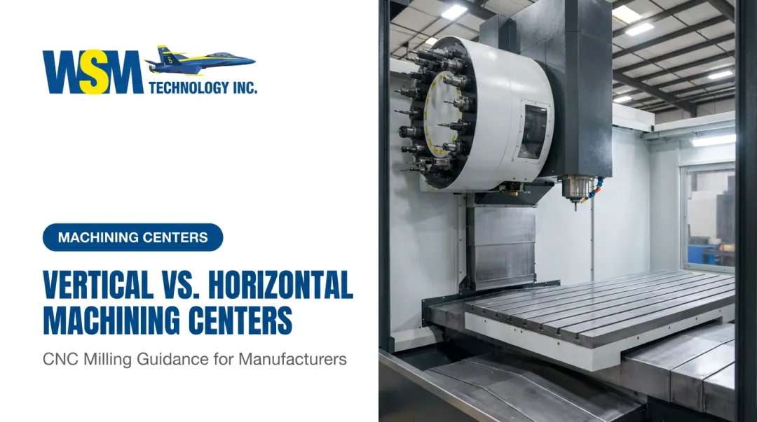
An HMC is a CNC machining center with its spindle oriented parallel to the floor. Rather than approaching the workpiece from above, the cutting tool engages from the side — and that orientation drives nearly every advantage the platform offers in aerospace production.
Chips fall away from the cutting zone by gravity instead of accumulating on the workpiece and fixture. For tough aerospace alloys that generate large, heat-retaining chips, this gravity-assisted chip evacuation actively protects the cutting zone, the tooling, and the finished surface.
Standard HMC Architecture
A production HMC typically includes:
- Horizontal spindle with side-entry tool engagement
- Twin-pallet system — one pallet machines while the other loads, eliminating idle time
- Automatic tool changer (ATC) with high-capacity magazine (60+ tools standard) — this is what separates a machining center from a milling machine: CNC mills cut, but machining centers cut and manage their own tooling automatically
- Rotary B-axis table that indexes the workpiece through multiple orientations without re-fixturing
4-Axis vs. 5-Axis HMC Configurations
The architecture above defines what an HMC is. The axis configuration determines what it can actually cut. For aerospace work, two setups are most relevant:
- 4-axis HMC: Adds a rotary B-axis to the standard X/Y/Z travels, allowing the workpiece to be indexed and machined on multiple faces in a single setup. Handles the majority of structural and housing components.
- 5-axis HMC: Adds a second rotary axis for continuous simultaneous cutting — necessary for impeller-type parts, complex contoured surfaces, and airfoil features requiring smooth 3D toolpaths.

Why Horizontal Machining Centers Excel in Aerospace Manufacturing
The HMC's advantages over vertical machining centers aren't theoretical. They're mechanical consequences of spindle orientation that compound when you're running aerospace alloys across multi-shift production runs.
Chip Evacuation in Aerospace Alloys
Titanium and Inconel generate large, tough chips that retain heat. On a vertical machining center, those chips pile up on the workpiece and fixture, recut against the part surface, introduce thermal energy into the cutting zone, and accelerate tool wear.
On an HMC, gravity clears chips continuously. The cutting zone stays cleaner, temperatures stay lower, tool life extends, and coolant demands drop — without any operator intervention.
Twin-Pallet Systems and Spindle Utilization
Every minute a spindle isn't cutting is lost capacity. On a conventional single-pallet setup, loading and unloading a complex aerospace part can consume 10–20% of total cycle time.
Twin-pallet HMCs eliminate this. While one pallet is machining, an operator stages the next workpiece on the second pallet. The machine never waits. According to DMG MORI, automated tool and pallet handling can increase productive spindle hours from roughly 2,000 to more than 6,000 per year compared with stand-alone installations — a threefold improvement that directly impacts delivery schedules on tight aerospace contracts.
Multi-Face Access Without Re-Fixturing
Aerospace structural components — bulkheads, housings, brackets — require machining on four, five, or six faces. On a VMC, each face typically requires its own setup: unclamp, reposition, re-indicate, re-clamp.
Every setup transition introduces its own error stack. Tolerances that are achievable on a single setup become harder to hold across four separate fixturing operations.
An HMC's rotary table indexes the workpiece through all required orientations without removing it from the machine. The datum stays fixed throughout, so positional accuracy across faces is maintained by the machine's geometry — not by how carefully an operator re-indicated the part.
Rigidity, Thermal Stability, and Automation Compatibility
Production HMCs are built for sustained, high-torque cutting in hard materials. Several design features work together to maintain positional accuracy across long production runs:
- Heavier castings and tiered column structures dampen vibration during aggressive cuts
- Closed-loop thermal compensation — such as Mazak's Ai Thermal Shield and Okuma's Thermo-Friendly Concept — corrects for spindle growth automatically
- Integrated coolant systems manage heat at the cutting zone, not just downstream
Makino's MMC2 linear pallet pool supports up to 200 pallets and helps manufacturers achieve up to 95% spindle utilization, making HMCs the backbone of lights-out aerospace cells. That level of automation supports the consistent, documented quality data — SPC records, FAI packages — that AS9100D certification requires.
Common Aerospace Components Machined on HMCs
Structural Airframe Components
The most natural HMC application in aerospace is large aluminum structural work. Bulkheads, wing ribs, fuselage frames, seat rail supports, and brackets share common characteristics:
- Large surface areas requiring significant material removal
- Multiple bolt-hole patterns spread across several faces
- Machining required on three or more faces in a single setup
Makino's MAG-Series 5-axis HMCs, for example, are built for medium-to-large aluminum airframe components, with the MAG3 running a 33,000 RPM, 130 kW spindle built for complex aluminum monolithic parts. The T4 targets large titanium structural parts — edge frames, pylons, and bulkheads — with a 1,000 Nm continuous spindle and 7 MPa high-pressure coolant.
Engine and Propulsion Components
Engine hardware is a strong fit for HMC work. Parts like these share box-like geometry with features on multiple faces — exactly where a rotary table delivers its biggest advantage:
- Compressor housings and turbine casings
- Combustion chamber rings
- Actuator bodies and surrounding structural hardware
Turbine blades themselves often require 5-axis VMC or EDM finishing, but the hardware around them runs productively on HMCs.
Landing Gear and Hydraulic Assemblies
Heavy landing gear components — axle beams, torque links, clevis assemblies, hydraulic manifolds — demand high-torque material removal in hardened steel and titanium. The HMC's rigid spindle, large work envelope, and pallet changers enable long-running unattended cycles on these parts. The Matsuura MAM72-100H, for instance, is built for titanium and Inconel in large, complex aerospace configurations.
HMC vs. VMC: Which Is Right for Aerospace Applications?
VMCs dominate the installed base — vertical machining centers held 47.68% of the machining centers market in 2025, per Mordor Intelligence. They're lower cost, easier to learn, and perfectly capable for the right applications. But market share doesn't equal best fit for every job.
Side-by-Side Comparison
| Factor | VMC | HMC |
|---|---|---|
| Spindle orientation | Vertical (tool from above) | Horizontal (tool from side) |
| Chip management | Chips accumulate on workpiece | Gravity clears chips |
| Setups per complex part | Multiple (one per face) | Single setup, multi-face via rotary table |
| Pallet automation | Limited; less common | Standard twin-pallet; pallet pools available |
| Tool magazine capacity | Typically 20–40 tools | 60–363 tools (DMG MORI INH range) |
| Floor space footprint | Compact | Larger |
| Best use case | Simple/single-face parts, prototypes | Multi-sided production parts, aerospace structures |

When VMCs Are the Right Choice
VMCs remain appropriate for:
- Simple 2D or single-face parts that don't require multi-side access
- Prototype work or low-volume jobs with varied geometry
- Smaller shops where initial investment is the binding constraint
- Parts where one-face machining captures most of the work content
The HMC Productivity Case
Modern Machine Shop documented a case where four-axis horizontal machining at McKenzie CNC cut operations and cycle times for high-mix, high-repeat work, more than doubling productivity compared with their previous approach.
The same dynamic plays out across aerospace shops running medium-to-high volumes of complex, multi-sided structural or housing components. In those environments, HMCs justify their higher purchase price through three compounding advantages:
- Higher spindle utilization — less time spent repositioning and re-fixturing between operations
- Lower setup error accumulation — single-setup machining eliminates tolerance stack-up across faces
- Automation compatibility — twin-pallet systems and pallet pools reduce operator intervention per part
Key Features to Look for in an Aerospace-Grade HMC
Spindle Specifications
Aerospace alloys span a wide cutting-condition range, and spindle selection needs to match your material mix:
- Aluminum structural work: High-RPM spindles (20,000–33,000 RPM) maximize metal removal rate. The Makino MAG3's 33,000 RPM/130 kW spindle is the reference point for high-rate aluminum work.
- Titanium and Inconel: High-torque spindles matter more than speed. The Makino T4 delivers 1,000 Nm continuous; the DMG MORI INH 63/80 offers 808 Nm at 12,000 RPM; the Kitamura HX800G reaches 1,226 Nm.
- Duty-rated vs. peak: Always confirm continuous-rated output, not peak. Peak ratings don't reflect sustained production performance.
- Spindle core cooling: Prevents thermal growth from migrating into part tolerances during long runs.

Axis Travel, Pallet Size, and Rotary Table
Match machine geometry to your actual parts before specifying:
- Confirm X, Y, and Z travels accommodate the full envelope of your largest component plus tooling clearance
- Pallet dimensions must fit your fixture plate and workpiece without overhang
- Direct-drive rotary tables improve indexing accuracy and allow shorter tooling on deep features — both critical for positional accuracy across multiple faces
Tool Magazine Capacity and Automation Compatibility
Aerospace parts are tool-intensive — roughing, semi-finishing, finishing, drilling, tapping, and boring each require dedicated tools. Look for:
- 60+ tool positions standard (the DMG MORI INH series starts at 63, extends to 363)
- Matrix magazine options of 130+ tools for long unattended runs
- Confirmed compatibility with pallet pool or robotic automation for lights-out operation
Control System and Thermal Compensation
On long aerospace production runs, thermal drift is the primary driver of dimensional error. The control system needs to correct for it continuously:
- Thermal compensation algorithms that model and correct for heat-related positional changes
- In-process probing cycles that auto-correct for drift without stopping the machine
- Real-time tool wear monitoring to flag tool changes before parts go out of tolerance
- Support for quality data export that feeds AS9100D documentation requirements
Dealer Support and Test-Cut Capability
Inadequate dealer support on an aerospace-production HMC means unplanned downtime during the runs where you can least afford it. Before purchasing, verify you can:
- Run test cuts on the actual machine with your actual material and part geometry
- Review cycle time data and surface finish results before committing
- Reach a factory-trained service technician quickly when something goes wrong
That last point matters more than most buyers anticipate. WSM Technology's Demonstration Center in Rootstown, Ohio gives manufacturers across Northern Ohio, Western Pennsylvania, and West Virginia a straightforward way to test against published specs — run your actual material, your actual part geometry, and review cycle time data before committing to a capital purchase.

Choosing the Right HMC Partner for Aerospace Production
A machine specification is a starting point. What happens after delivery determines whether that specification translates into production performance.
For an AS9100D-certified aerospace shop, HMC downtime isn't just a maintenance problem. It disrupts delivery schedules, triggers customer inquiries, and can put contract status at risk. The dealer's response infrastructure matters as much as the machine's feature list.
What to Look for in a Regional Dealer
- Factory-trained service technicians with OEM authorization, not third-party generalists
- Stocked OEM replacement parts available without extended lead times
- Applications engineering support — someone who can diagnose a process problem, not just a machine problem
- Demonstrated aerospace or regulated-industry experience (medical, defense shops are comparable in quality system rigor)
- Willingness to run prove-out cuts on representative parts before the purchase order is signed
WSM Technology serves as the MC Machinery/Mitsubishi representative across Northern Ohio, Western Pennsylvania, and West Virginia, with factory-trained support and a Demonstration Center in Rootstown, Ohio for hands-on machine evaluation. Founder Blaise Buholzer began his career as an application engineer on wire and die-sinker EDM machines, giving the team the process-level depth aerospace shops need — not just equipment sales.
Questions to Ask Before Signing a Purchase Order
- Can I run a test cut on this specific machine with my actual part material?
- What is your typical service response time for a production breakdown in my area?
- Do you have references from aerospace or defense shops in this region?
- What does your thermal compensation system maintain over an 8-hour unattended run?
- How are OEM replacement parts stocked and sourced locally?
A dealer who hesitates on any of those answers — or can't point to regional aerospace references — is telling you something worth knowing before you commit.
Frequently Asked Questions
What is a horizontal machining center?
A horizontal machining center is a CNC machine tool with its spindle oriented parallel to the floor, so the cutting tool approaches the workpiece from the side. Chips fall away by gravity, and production HMCs include twin-pallet changers and automatic tool changers designed for high-efficiency, often unattended operation.
What is the difference between VMC and HMC?
A VMC (vertical machining center) has a downward-pointing spindle: lower cost and easier to learn, but chips accumulate on the workpiece and multi-sided parts require multiple setups. An HMC's horizontal spindle, rotary table, and pallet changers enable multi-face machining in one setup with better chip evacuation and significantly higher spindle utilization.
What is CNC in aerospace?
CNC in aerospace refers to computer-controlled machine tools used to produce flight-critical components to micron-level tolerances. Production operates under certified quality systems such as AS9100D and NADCAP, with full traceability documentation at every stage.
What aerospace components are best suited for HMC machining?
Structural airframe parts (bulkheads, wing ribs, fuselage frames), engine housings, compressor casings, landing gear components, and hydraulic manifolds are ideal HMC candidates. They share multi-sided geometry, tight tolerances, and high material removal requirements in aerospace alloys.
What tolerances can horizontal machining centers achieve for aerospace parts?
Modern aerospace-grade HMCs routinely hold ±0.001 in (25 µm) for structural parts, with tighter tolerances achievable on engine-adjacent components. Thermal compensation and in-process probing sustain this accuracy across long production runs without manual correction.
Do I need a 4-axis or 5-axis HMC for aerospace work?
A 4-axis HMC covers most aerospace structural and housing work, indexing the workpiece to multiple faces via the rotary B-axis. A 5-axis HMC adds a second rotary axis for continuous simultaneous cutting, which is required for impeller profiles, contoured surfaces, and airfoil features that need smooth 3D toolpaths.