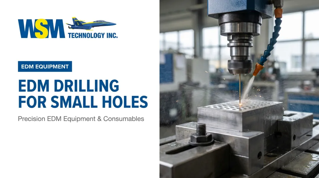
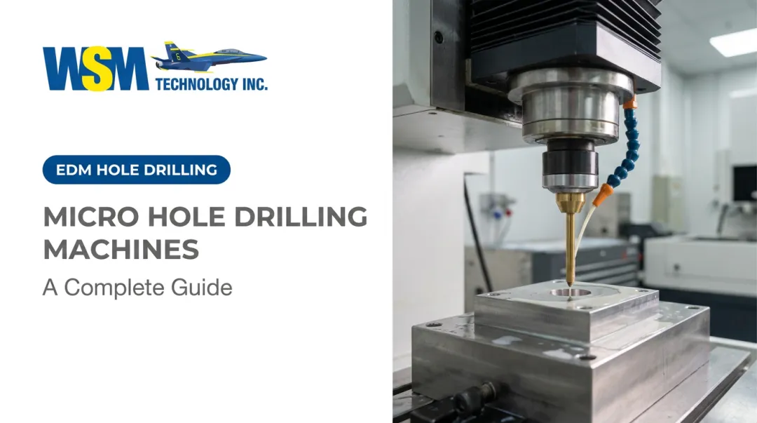
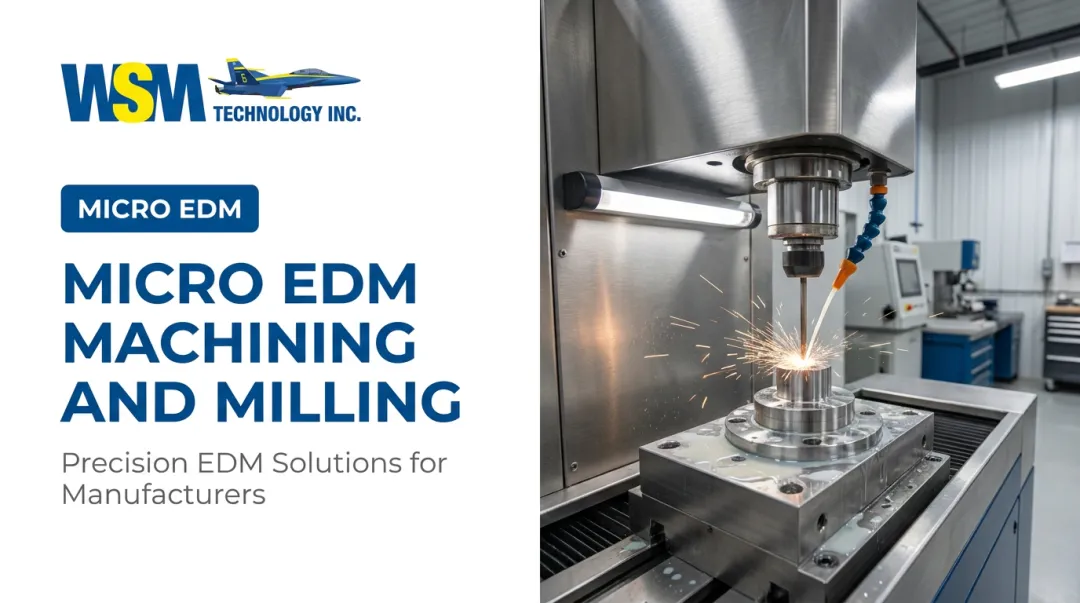
For mold and die makers, and shops serving medical, electronics, and aerospace customers, this process is often the difference between a part that meets print and one that gets scrapped. Tight tolerances leave no room for guesswork.
Here's the problem: micro drilling gets referenced constantly in shop conversations, but the operational details, RPM, coolant strategy, tool selection, are frequently misunderstood. This guide breaks down how the process actually works, what affects the outcome, and when it's the right call.
Key Takeaways
- Micro drilling covers holes 3 mm or smaller, with specialty tools reaching 10-20 microns
- It's essential for mold venting, medical components, and fuel/nozzle bores needing tight tolerances
- Success depends on machine rigidity, tool geometry, and coolant delivery working together
- For extremely hard, brittle, or ultra-fine work, micro EDM often outperforms mechanical drilling
What Is Micro Drilling and Why It's Used in Precision Manufacturing
Micro drilling is a mechanical process that uses solid carbide or high-speed steel (HSS) twist drills, typically running on high-speed, low-runout spindles, to bore holes 3 mm in diameter or smaller. Depths can run 20 times the diameter or more on certain tool families.
The goal sounds simple: produce a clean, precise hole, through or blind, without introducing thermal damage, burring, or dimensional drift. In high-value components, even a small deviation can mean a rejected part.
Micro drilling isn't the only way to make a small hole. Related processes include:
- Micro EDM – uses electrical discharge (spark erosion) instead of cutting, better suited to very hard or ultra-small holes
- Laser drilling – thermal ablation, useful on thin materials or where mechanical stress must be avoided
- Micro punching – mechanical shearing, fast for high-volume thin-sheet work
Manufacturers reach for mechanical micro drilling over these alternatives for one main reason: faster cycle times and lower cost per hole on standard metals and plastics within its size range.

What Precision Manufacturing Demands
Shops running micro drilling in production need consistency across thousands of holes, minimal burring, and tolerances measured in microns, not thousandths of an inch. That's a different standard than general-purpose drilling.
Industry sources describe micro drilling broadly as holes smaller than 3 mm, though exact boundaries vary by manufacturer. Sphinx, as cited by Production Machining, defines its own micro-drilling range even tighter, from 0.05 mm to 2.5 mm. There's no single ISO standard, just an industry convention.
Without disciplined practice, things go wrong fast. DATRON's documented experience drilling 0.008-inch holes in 15-5 PH stainless steel found that re-cut chips and coolant pressurization inside the hole caused repeated tool breakage. The fix required full retraction on every peck cycle, a small but critical process adjustment.
How the Micro Drilling Process Works
At a high level, the process flows through four stages: setup and tool selection, controlled entry, coolant-assisted cutting, and controlled retraction.
Process inputs include:
- The workpiece material (hardness, machinability, thermal conductivity)
- A precision micro drill, carbide or HSS
- A low-runout spindle or dedicated machine
- A coolant delivery system
- Programmed cutting parameters (speed, feed, peck depth)
The cutting action itself is straightforward in concept: the drill's cutting edges shear material into chips while coolant manages heat and flushes debris out of flute channels that may only be a few microns wide. At this scale, a clogged flute can snap a tool in seconds.
Avoiding that failure depends on control: pecking cycles, spindle speed matched to material hardness, and feed rates calibrated so the fragile tool never gets overloaded. The result: a hole cut to precise diameter and depth, while the tool itself accumulates wear that has to be tracked cycle over cycle.
The process then unfolds in three steps:
- Pilot drilling and setup: For deeper holes, often those beyond 12 times the diameter, a pilot drill establishes an accurate, low-wander entry point before the primary tool engages. Harvey Performance recommends a pilot up to 1.5 times the diameter for this purpose, though shallower holes frequently skip this step since drift risk is lower.
- Primary drilling at controlled speed: The primary drill enters the pilot hole at reduced RPM, then ramps to nominal cutting speed once engaged. Through-coolant activates at a pressure range suited to the tool and material, keeping chips flowing and heat from building in the flutes.
- Retraction and inspection: Once the target depth is reached, RPM drops and the tool fully retracts. Operators then inspect for wear indicators such as edge chipping, discoloration, and buildup before starting the next cycle. Skipping this step is how a single worn tool turns into a batch of scrapped parts.

Where Micro Drilling Is Applied and What Affects the Process
Micro drilling runs on high-speed CNC machining centers, dedicated micro drilling machines, and air-bearing spindle setups. Not every CNC platform qualifies. The spindle and toolholder combination has to hold runout tight enough to keep a fragile tool alive.
WSM Technology's shop floor experience shows both approaches in action. The Roku-Roku Android II runs a 60,000 RPM spindle with an HSK-E25 interface and holds ±1 micron machining accuracy, backed by 16 thermal sensors and active heat isolation.

That's the mechanical side of the equation. For applications that push past what mechanical drilling can reliably deliver, Sarix Micro EDM systems handle micro hole drilling through spark erosion instead.
Common lifecycle points for micro drilling include:
- Mold and die making (venting and cooling holes)
- Fuel injection and nozzle bore production
- Medical device manufacturing
- Electronics connector holes
- R&D prototyping
Most of this work is production-embedded, running thousands of identical holes per batch, though one-off precision prototypes use the same process at lower volume.
Factors That Affect the Outcome
- Material properties – hardness, machinability, and thermal conductivity dictate drill material and cutting speed
- Operating conditions – spindle runout, coolant type and pressure, and ambient temperature stability all matter
- Equipment dependencies – precision toolholders and machine rigidity are non-negotiable; standard CNC setups often can't hit required speeds without excess vibration
- Scale and throughput – some parts need thousands of holes per run, making tool life and cycle time critical cost drivers
- Aerospace and medical constraints – documented tool reconditioning schedules are often required to meet quality and traceability standards
Runout matters more than most shops assume. A documented test by BIG Daishowa found a 3 mm carbide drill produced 148 holes at 80 microinches of runout, three times its life compared to running at 0.0006 inch. Same tool, same material, wildly different outcome.
Optimized parameters pay off too. OSG reports roughly 5x drilling efficiency and 2x tool life with its ADO-MICRO coolant-through design compared to standard tooling in specified tests.
Common Issues, Misconceptions, and When Micro Drilling May Not Be the Right Fit
Standard drilling practices don't transfer cleanly to the micro scale. Spindle types, pecking strategies, even feed rate assumptions built for conventional drilling break down once tool mass drops and runout sensitivity goes up. A 6 mm drill tolerates vibration that would snap a 0.3 mm tool instantly.
That fragility also feeds a common oversimplification: assuming any CNC machine can "micro drill" simply because it can hold a small tool. In reality, consistent results require precision toolholders and low-runout, high-speed spindles built for the job, not a general-purpose mill pressed into service.
There's also a persistent myth that mechanical drilling hits a hard wall around 30 microns. That's not quite accurate. Standard catalog tools from major manufacturers reach into the 10-20 micron range already. The real crossover point depends more on material hardness and brittleness than diameter alone:
- Extremely hard or brittle materials often favor micro EDM over mechanical cutting
- Ultra-thin wafer substrates can crack under mechanical drilling stress
- Very fine hole diameters combined with hard alloys frequently push shops toward EDM or laser processes

Even when micro drilling is technically feasible, the warning signs of a poor fit usually show up on the shop floor first. If a shop is seeing chronically high tool breakage or scrap rates, that's usually a signal micro drilling is being used by default rather than by genuine fit. Before spending more on tooling, a time study or process evaluation often reveals whether the issue is parameters, equipment, or process selection entirely.
Conclusion
Micro drilling is a precision mechanical process for producing small, high-tolerance holes. It sits at the center of mold, medical, electronics, and aerospace manufacturing.
Getting it right depends less on the machine that happens to be free and more on matching tool selection, coolant strategy, and machine capability to the application.
Before committing tooling budget to a micro drilling setup, weigh whether mechanical drilling, micro EDM, or another process fits the material and tolerance better. WSM Technology's demonstration center in Rootstown, Ohio helps make that call with real data instead of guesswork through:
- Test cuts across milling, EDM, and CNC platforms
- Time studies to benchmark cycle times and capability
- Application engineering support to match process to part
Frequently Asked Questions
What is micro drilling?
Micro drilling produces holes typically 3 mm in diameter or smaller using precision drill bits and high-speed, low-runout machines. It's a mechanical cutting process, distinct from thermal methods like EDM or laser drilling.
How are micro drills made?
Manufacturers grind micro drills from solid carbide or high-speed steel, adding precise micro-geometry, specialized coatings, and fine internal coolant channels. Manufacturing tolerances at this scale are extremely tight, often within a few microns.
What is the smallest hole diameter that can be micro drilled?
Standard mechanical micro drills reach diameters as small as roughly 10-20 microns from some manufacturers. Below that range, processes like micro EDM, laser drilling, or punching generally take over.
What materials can be micro drilled?
Common materials include carbon steel, stainless steel, aluminum, non-ferrous alloys, and select hardened or superalloy materials. Hardness and thermal conductivity strongly influence tool material and cutting speed selection.
What's the difference between micro drilling and micro EDM?
Micro drilling is a mechanical cutting process, while micro EDM uses electrical discharge erosion to remove material without physical cutting force. EDM is generally better suited to very hard materials or ultra-fine hole applications.
What RPM is needed for micro drilling?
Speeds vary widely based on material and drill diameter, with documented examples ranging from roughly 15,000 to 17,000 RPM for specific steel and stainless applications. Always follow manufacturer-specific cutting data rather than a generic figure.