Introduction
Internal gear grinding is a post-heat-treatment precision finishing process that uses an abrasive wheel to achieve tight tolerances on the inward-facing tooth surfaces of ring gears.
If you work in gear production, transmission engineering, or precision manufacturing, you already know the problem: heat treatment fixes the metallurgy but distorts the geometry. Gears that passed inspection before the furnace come out with pitch errors, profile deviations, and lead variation significant enough to generate noise and reduce service life.
Soft machining alone cannot fix this — grinding after heat treatment can.
This article covers:
- How the internal gear grinding process works
- The two primary techniques used in production
- Industries and applications where the process is most critical
- The variables that most directly affect finished gear accuracy
Key Takeaways
- Corrects heat-treatment distortion in ring gears to achieve high accuracy classes (JIS class 4 and above)
- Two techniques exist: generating grinding for high-volume involute profiles; form/profile grinding for complex or non-standard geometries
- Primary applications include automotive planetary transmissions, aerospace actuator gearboxes, industrial robotics, and wind turbine planetary gearboxes
- Wheel-inside-bore constraints limit diameter, rigidity, coolant access, and dressing intervals
- CNC synchronization accuracy and thermal stability determine whether the process holds tolerance
What Is Internal Gear Grinding?
Internal gear grinding is a precision abrasive machining operation applied to the inward-facing tooth surfaces of ring gears (internal gears). It is performed after heat treatment to correct the dimensional distortion hardening introduces.
The outcome the process targets is measurable and specific:
- Corrected tooth profile — eliminating involute deviation introduced by thermal distortion
- Corrected lead — restoring the helical path of the tooth across face width
- Corrected pitch — removing spacing errors between adjacent teeth
- Improved surface finish — reducing Ra values to levels that minimize friction and noise
Research documented by Mitsubishi Heavy Industries and Gear Solutions shows that thin-walled ring gears typically arrive from heat treatment at JIS class 10–11, and can be ground to JIS class 4 — an accuracy improvement that directly reduces transmission noise and vibration.
How Internal Gear Grinding Differs from External Grinding
External gear grinding works on outward-facing tooth surfaces with a wheel that has open access to the contact zone. Those geometry and access advantages disappear when grinding internal gears — the wheel must operate inside a confined bore, imposing constraints that don't exist in external work:
- Wheel diameter must stay smaller than the bore, limiting stiffness and increasing deflection sensitivity
- Visual inspection of tooth meshing is obstructed
- Coolant delivery to the contact zone is restricted
- Dressing intervals shorten because smaller wheels wear faster relative to the workpiece
Each constraint compounds the others, which is why internal gear grinding demands tighter process control and more specialized tooling than external grinding.
How Internal Gear Grinding Works: Techniques and Process
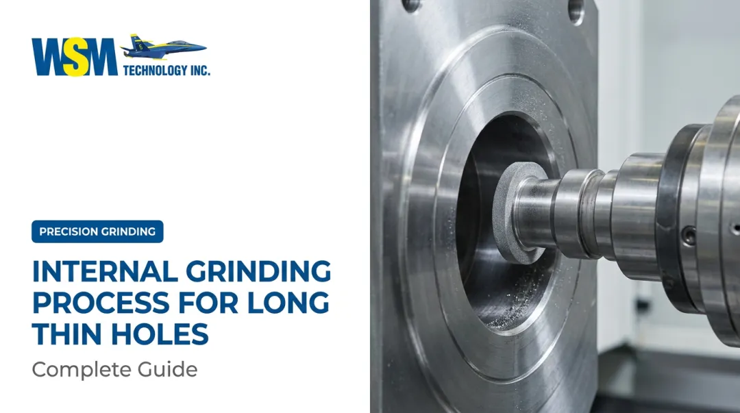
The ring gear is fixtured on the machine table and the grinding wheel is positioned inside the bore. Synchronous rotation of both the wheel and workpiece generates the desired tooth geometry through controlled abrasive contact. Which of the two primary techniques is used determines how that contact is achieved.
Generating Grinding
Generating grinding (also called continuous generating or worm grinding) uses a multi-threaded, worm-like grinding wheel that meshes with the internal gear in a generating motion. The wheel spindle and workpiece table rotate synchronously at high speed. A crossed-axis angle of 20–35° between the wheel axis and workpiece axis increases sliding velocity at the contact point, which improves surface finish, grinding accuracy, and tool life.
MHI's internal gear grinding systems use barrel-shaped threaded wheels to avoid interference at the wheel-width ends as the crossed-axis angle increases. This geometry-specific design choice reflects how different internal gear grinding is from scaling down an external grinding setup.
Wheel and dressing options for generating grinding:
- Vitrified or CBN grinding wheels (CBN preferred for hardened steels due to thermal stability and longer dress life)
- Master/diamond dressing gear: electroplated with diamond to match workpiece geometry; faster and simpler for fixed profiles
- CNC disk-type dresser: dresses one tooth profile at a time and supports flank modification and profile corrections
The disk dresser adds flexibility for tooth profile modification at the cost of cycle time. The master dresser is faster but locks the operator into a fixed geometry. The right choice depends on whether the application calls for standard involute profiles or modified flanks.
Generating grinding is the dominant method for high-volume automotive ring gear production. It is fast, consistent, and capable of maintaining tight accuracy across long production runs. Where it reaches its limits — non-standard profiles, small batches, large-module gears — form grinding takes over.
Form/Profile Grinding
Form grinding dresses the wheel to match the exact tooth space profile of the ring gear. The dressed wheel then traverses axially to grind one or two tooth spaces at a time. An electroplated diamond tool shapes the wheel to the required profile.
This method is better suited to:
- Small batches and individual parts
- Non-standard profiles (cycloidal, spline, harmonic drive geometries)
- Large-module internal gears where generating wheel geometry becomes impractical
- Applications requiring highly modified tooth geometry
The trade-off is efficiency. Form grinding offers greater geometric flexibility but lower throughput and higher tooling cost per piece compared to generating grinding.
| Factor | Generating Grinding | Form/Profile Grinding |
|---|---|---|
| Best for | High-volume involute profiles | Small batches, complex profiles |
| Throughput | High | Lower |
| Profile flexibility | Limited (modification via disk dresser) | High |
| Tooling cost per piece | Lower at volume | Higher |
| Typical application | Automotive planetary ring gears | Aerospace, robotics, specialty gears |

Key Process Steps
Step 1 — Pre-grind inspection and setup The ring gear arrives from heat treatment. The operator measures pre-grind distortion (typically JIS class 10–11 for thin-walled components). The gear is fixtured, and an automatic tooth-meshing system using non-contact or acoustic emission sensors aligns the wheel to the existing tooth spaces. This alignment step is more complex than in external grinding because the bore obstructs direct visual verification.
Step 2 — Rough and semi-finish grinding passes The machine removes the bulk of post-heat-treat material in multiple passes at programmed feed rates and depths. CNC axes control radial feed, axial stroke, and rotational synchronization to maintain the involute tooth profile throughout material removal.
Step 3 — Finish grinding and dressing cycle Final passes achieve the target tooth profile, lead, and surface finish. The grinding wheel is re-dressed at programmed intervals. The cycle concludes with in-process or post-process gear measurement to verify the target accuracy class is met.

Where Internal Gear Grinding Is Applied
Internal gear grinding is used wherever ring gears must meet high accuracy and surface quality requirements after hardening — applications where noise, load capacity, and dimensional consistency cannot be traded against production convenience.
Automotive Transmissions
Automatic and hybrid vehicle planetary gear systems represent the largest single application for internal gear grinding. Ring gears in these systems are case-hardened and then ground to eliminate the noise and vibration that soft-machined gears cannot adequately control.
High volumes, consistent quality, and tight cycle time targets make generating grinding the dominant method in this sector. The process suits the continuous, repeatable production that automotive lines demand.
The global electric vehicle market is projected to reach USD $12,600 billion by 2033 at a 26.7% CAGR, and EV powertrains place even stricter noise and efficiency demands on ground ring gears than conventional automatic transmissions do. Gear Technology has noted that generating grinding requirements are tightening specifically to meet EV NVH and efficiency targets.
Aerospace and Defense
Aerospace actuators, helicopter gearboxes, and auxiliary drive systems require internal gears that meet tight dimensional tolerances and strict surface integrity standards. Small batch sizes, tight quality documentation requirements, and non-standard tooth geometries make form/profile grinding more common in this sector than generating grinding.
Surface integrity — the condition of the tooth surface and the subsurface metallurgy beneath it — is a particular concern in aerospace applications. Any grinding burn that alters residual stress or microstructure is cause for rejection, so aerospace grinding typically requires Barkhausen noise inspection or nital etch verification as part of the process.
Industrial and Emerging Applications
Several additional sectors are driving increased demand for internal gear grinding capability:
- Industrial robotics — Harmonic drives and cycloidal reducers require internal gears with zero-backlash tooth profiles and exceptional accuracy — Liebherr has documented internal profile grinding of roller seats on inner rings for exactly these components
- Wind turbine planetary gearboxes — KAPP NILES's ZPI machines grind internal ring gears in planetary gearboxes with outer diameters up to 5,000 mm; the wind turbine market is projected to reach USD $164.3 billion by 2033
- Precision machine tool spindles — High-accuracy rotary components requiring tight bore geometry

Key Factors That Affect Internal Gear Grinding Quality
Because the grinding wheel operates inside a confined bore, small errors in any process variable are amplified compared to external gear grinding. These are the variables that matter most.
Grinding Wheel Selection and Sizing
The wheel diameter must be significantly smaller than the bore, which limits wheel stiffness and contact area. A larger wheel within the bore improves rigidity and material removal rate but increases the risk of interference. Vitrified CBN (cubic boron nitride) wheels are the preferred choice for hardened steel ring gears — they offer superior thermal stability, wear resistance, and consistent profile accuracy compared to conventional aluminum oxide wheels.
Smaller internal grinding wheels also wear faster relative to the workpiece, which means dressing intervals must be more frequent than in external gear grinding. Automated dressing cycles on CNC grinders minimize cycle time impact while maintaining wheel profile integrity.
Center Offset and Wheel Alignment
In form grinding, misalignment between the grinding wheel center and the workpiece center causes asymmetric tooth profile errors — uneven left/right flank deviations that cannot be corrected by subsequent passes without re-dressing. CNC-controlled axis adjustments during dressing correct this offset. Even sub-millimeter misalignment at small modules creates measurable quality defects, which is why precise CNC synchronization is non-negotiable.
Radial Feed and Pressure Angle Accuracy
Deviations in radial feed — caused by wheel wear or thermal expansion of the spindle or machine structure — shift the effective pressure angle of the ground tooth. CNC machines with real-time feedback can detect and correct these deviations mid-cycle.
Machines that lack adequate thermal stability or axis synchronization accuracy will produce inconsistent pressure angles across a production run, even when all other parameters are correctly set. This is why high-precision CNC machine tools are non-negotiable for internal gear grinding — not just for accuracy, but for consistency across volume production.
WSM Technology carries Danobat OD/ID grinders and Overbeck external/internal grinders, both engineered for the thermal stability and synchronization accuracy these applications require. Those same thermal concerns extend into the cutting zone itself, where coolant access becomes the next critical variable.
Coolant Management and Thermal Effects
Internal grinding geometry restricts coolant access to the contact zone, raising the risk of grinding burn — thermal damage that alters microstructure, residual stress, and surface hardness. Managing this requires:
- Optimized coolant flow rate and nozzle positioning
- Appropriate wheel speed selection
- Monitoring for burn indicators, particularly when grinding carburized or case-hardened ring gears
Burn on a ground gear tooth is not always visible. Nital etch testing and Barkhausen noise analysis are commonly used to verify that thermal damage has not occurred below the surface.

Common Challenges and Misconceptions
"Grinding Gears" vs. Gear Grinding
The phrase "grinding gears" in everyday automotive language describes a noise — typically caused by worn synchronizers, clutch failure, or damaged gear teeth in a manual transmission. The two uses of the term appear in completely different contexts, but the overlap causes confusion for people new to either subject.
Internal Gear Grinding Is Not Just External Grinding with a Smaller Wheel
Manufacturers new to internal gear grinding often assume the process is a straightforward adaptation of external gear grinding. It is not. The distinct challenges include:
- Wheel interference constraints that limit available wheel geometry
- Reduced wheel rigidity affecting surface finish and form accuracy
- More frequent dressing requirements that affect cycle time and tooling cost
- More complex tooth-meshing alignment that cannot rely on visual verification
- Restricted coolant access that increases thermal risk
Underestimating these differences leads to poor process planning, inadequate machine selection, and quality problems that are genuinely difficult to diagnose once they appear.
Defaulting to Form Grinding for All Internal Gear Work
A related assumption is that form grinding is always the safer or more precise choice for internal work. For involute profiles in moderate-to-high production volumes, generating grinding typically delivers better throughput, better repeatability, and equal or superior accuracy.
The correct method depends on:
- Production volume — generating grinding gains efficiency at scale
- Tooth profile complexity — non-involute or modified profiles may favor form grinding
- Flank modification requirements — crowning and lead corrections are more accessible with generating methods
Familiarity with one method is not a valid reason to default to it.
Conclusion
Internal gear grinding is a technically demanding but necessary finishing process for ring gears that must meet high accuracy, low noise, and long service life requirements after heat treatment introduces distortion that no soft machining process can fully correct.
Success comes down to a few controllable factors:
- Choosing between generating and form grinding based on production volume and tolerance requirements
- Selecting machine geometry and tooling suited to the bore diameter and access constraints
- Maintaining tight control over wheel alignment, radial feed, dressing frequency, and coolant delivery
Shops that approach internal gear grinding as a simple extension of external work quickly run into problems. The confined bore limits rigidity, restricts coolant flow, and amplifies thermal errors — all of which demand dedicated setup discipline rather than borrowed assumptions.
Frequently Asked Questions
What does it mean if a gear is grinding?
In an automotive context, a grinding sound signals a mechanical problem — worn synchronizers, clutch failure, or damaged gear teeth. It has nothing to do with the precision manufacturing process called internal gear grinding.
What is internal grinding?
Internal grinding is a broad category of cylindrical grinding performed on the inside surface of a bore or hole. Internal gear grinding is a specialized subset that focuses specifically on finishing the tooth profiles of ring gears to high accuracy standards after heat treatment.
What is the difference between form grinding and generating grinding for internal gears?
Form grinding dresses the wheel to match the tooth space profile and grinds one tooth at a time — better for complex profiles, large modules, and small batches. Generating grinding uses a synchronized worm-type wheel for continuous, high-speed, high-volume production of involute ring gears.
Why is internal gear grinding more difficult than external gear grinding?
The grinding wheel must fit inside the ring gear bore, limiting its diameter and reducing rigidity. This also increases dressing frequency, restricts coolant access to the contact zone, and makes tooth-meshing alignment verification more complex than in external grinding.
What industries most commonly use internal gear grinding?
Automotive planetary transmissions, aerospace actuator gearboxes, industrial robotics (harmonic and cycloidal drives), and wind turbine planetary gearboxes are the primary sectors — all applications where ring gear accuracy and surface quality directly affect system performance and service life.
What type of grinding wheel is best for internal gear grinding?
Vitrified CBN (cubic boron nitride) wheels are the standard choice for hardened steel ring gears. They deliver superior thermal stability, longer dress life, and consistent profile accuracy compared to conventional aluminum oxide wheels.