Get the codes right, and you get a clean part on the first pass. Get them wrong, and you're looking at wire breaks, oversized cavities, or a scrapped mold component that took hours to set up.
As Mitsubishi controls like the M700 and M800 add more axes and automation, the code sets behind them have grown more layered too. This guide breaks down the main categories of Mitsubishi wire EDM G-codes, how they differ, and how shops actually choose the right combination for a given job.
Key Takeaways
- G-codes control wire movement, offset compensation, and taper cutting in every program
- Three code categories matter most: positioning, offset compensation, and taper/multi-axis
- Part geometry, material thickness, and tolerance requirements determine which codes you need
- Incorrect offset or taper entries commonly cause dimensional errors and scrapped parts
- Hands-on training and test cuts from WSM Technology quickly reduce programming mistakes
What Are Wire EDM G-Codes?
G-codes are standardized preparatory commands that control machine motion and cutting functions. In wire EDM, they tell the control where the wire travels, how fast, and in what shape.
Mitsubishi's control platforms, including the M700 and M800 series, read these codes and translate CAM-generated output into actual wire path movement across the X, Y, U, and V axes. Each platform brings distinct capabilities:
- M700: Handles simultaneous four-axis operation with built-in 2D CAM and geometric program functions
- M800: Builds on that foundation with a 19-inch touchscreen, common-shape macros, and expanded job-management tools
Think of G-code as the bridge between your CAD/CAM file and the physical wire cutting metal. Every line in that file translates directly into machine behavior:
- Executes each rapid move, cutting pass, and offset applied during the job
- Determines the exact path, speed, and shape the wire follows
- Separates a program that runs clean from one that stalls, breaks wire, or produces an out-of-tolerance part
Understanding these codes isn't optional for anyone running production on a Mitsubishi wire EDM—programming errors here show up directly in part quality and wire consumption.

Why Are G-Codes Important in Wire EDM Machining?
Correct G-code programming directly affects part accuracy, surface finish, and cycle time. There's no way around it: the code is the process.
When G-codes are entered incorrectly, the failures tend to show up in predictable ways:
- Wire breakage during cuts, often tied to debris buildup in the kerf or wire deviation from the intended path
- Incorrect kerf sizing, where the finished feature doesn't match the drawing because offset values were off
- Tapering errors on angled walls, producing draft angles that don't match the die design
- Scrapped workpieces after hours of setup time, because a single line of code sent the wire somewhere it shouldn't have gone
A peer-reviewed study in the ASME manufacturing science journal identifies debris accumulation and wire deviation as core mechanisms behind wire breakage. Flushing conditions and path accuracy both matter, not just raw code entry.
As Mitsubishi machines add 4-axis and multi-axis taper capability, the code complexity climbs. A flat 2D contour program looks nothing like a 4-axis stamping die program. That's exactly why understanding the distinct code categories matters before you sit down to write one.
Types of Mitsubishi Wire EDM G-Codes
Wire EDM G-codes aren't one-size-fits-all. Mitsubishi's programming language groups codes by function, and each group handles a different piece of the machining puzzle. Combining them correctly, not just knowing them individually, is what produces an accurate, collision-free program.
Positioning and Interpolation G-Codes
These are the foundational motion codes present in virtually every wire EDM program:
- G00 — rapid/point-to-point positioning, moving the wire quickly between cutting locations
- G01 — linear interpolation, cutting a straight line at programmed speed
- G02/G03 — circular interpolation, cutting clockwise or counterclockwise arcs
These codes direct the wire path across the X-Y (and U-V) axes. They're not corrective or angular adjustments; they're the raw movement instructions everything else is built around.
Best suited for: any straight or arc contour job, from simple prototypes to standard 2D profiles.
Key strengths: universal, simple to program, and required in nearly every job file.
Limitations: on their own, G00-G03 can't account for wire diameter, spark gap, or angled walls. They have to be paired with offset and taper codes to produce a finished, accurate part. A perfectly programmed contour with no offset applied still won't match the print.
Wire Offset/Compensation G-Codes
Once the basic path is set, the machine needs to know how far to shift that path to account for the wire itself:
- G40 — cancels wire offset compensation
- G41 — applies compensation to the left of the programmed path (direction of travel)
- G42 — applies compensation to the right of the programmed path
These codes shift the toolpath mathematically. They don't change the raw motion; they correct it. Mitsubishi's M700 control supports up to 900 wire-offset numbers with a setting range of ±99,999.999 mm, giving programmers room to assign separate offsets for roughing and finishing passes on the same job.
Best suited for: precision dies, punches, and mold components requiring tight dimensional tolerances across multiple passes.
Key strengths: the finished part matches drawing dimensions regardless of wire diameter, and rough/finish passes can carry different offset values for progressively better surface finish.
Limitations: this only works if the entered wire diameter and spark gap values match what's actually loaded on the machine. Enter the wrong value, and the part comes out oversized or undersized. No amount of good motion programming fixes that after the fact.

Taper and Multi-Axis (4-Axis) G-Codes
This is where wire EDM programming gets genuinely complex. Taper codes enable independent upper and lower wire guide movement (U-V axis control), synchronized with X-Y motion, to cut angled walls.
Moving the upper guide relative to the lower guide inclines the wire, generating draft angles and relief clearances needed on:
- Stamping dies with punch clearance requirements
- Extrusion tooling with expanding or reducing profiles
- Mold components needing angled walls in a single setup
Mitsubishi's MV-series catalog specifies a standard maximum taper angle of 15 degrees, with an Angle Master guide kit and taper wire required to go beyond that, up to an optional 45 degrees on properly configured machines.
That's a meaningful ceiling to know before you promise a customer a steep-angle die in one setup. The machine's guide geometry and part thickness both limit what's actually achievable.
Best suited for: stamping dies, extrusion tooling, and any part requiring draft angles or profile changes without a second setup.
Key strengths: complex 3D geometry cut in one operation, cutting down handling time and eliminating secondary machining.
Limitations: taper programming is harder to do manually, and the risk of collision or angle-calculation error goes up fast. This is exactly why CAM-assisted programming has become standard for anything beyond simple angles.
Mitsubishi's own M800 control documentation notes that common-shape programming macros can cut programming time by as much as 88% on supported jobs, a strong signal of how much manual entry time automation removes from the equation. For genuine 4-axis die programs, that kind of automated assistance is risk management built into the workflow.
How to Choose and Verify the Right G-Codes for Your Job
The right G-code combination depends on the part in front of you, not on habit or what you programmed last week. Four factors drive the decision:
- Part geometry and angle requirements: a flat contour needs positioning and offset codes only; a tapered wall needs U-V axis control layered on top
- Material type and thickness: thicker material changes offset/kerf calculations and cutting speed settings, and it limits achievable taper angle
- Tolerance and surface finish requirements: tight tolerances mean separate rough and finish pass offset values, not one blanket number
- Control system compatibility: code syntax can vary between older FX-series controls and the current M700/M800 platforms, so don't assume a program written for one runs cleanly on the other
Before finalizing any program, run through this checklist:
- Verify wire diameter and spark gap entries match the actual consumables loaded on the machine
- Simulate the program to catch collisions in taper sections before the wire ever touches material
- Confirm corner control settings to prevent overburn on tight radii
- Validate complex programs with a test cut before committing to a full production run
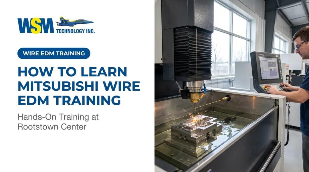
That last step matters more than most shops give it credit for. A test cut catches the offset or taper mistake on a scrap block instead of on the customer's mold steel. WSM Technology runs test cuts and time studies through its Rootstown, Ohio demonstration center specifically for this reason. Programs get proven out on an actual Mitsubishi machine before hitting the shop floor. When a program needs troubleshooting, local training and application engineering support are available to help.

Conclusion
G-codes are the language behind every cut a Mitsubishi wire EDM machine makes. Positioning codes handle raw motion. Offset codes correct for wire diameter and spark gap. Taper codes add the angular, multi-axis coordination that stamping and extrusion dies demand.
None of these categories work in isolation. Accurate, efficient parts come from combining them correctly for the geometry, material, and tolerance in front of you.
Whether you're programming manually or relying on CAM automation for a 4-axis die, mastering these fundamentals pays off directly in part quality and shop uptime. Partnering with a dealer like WSM Technology, who can train your team and prove out programs before production, adds another layer of confidence to that investment.
Frequently Asked Questions
What is the difference between G40, G41, and G42 in wire EDM programming?
G40 cancels wire offset compensation. G41 applies left-hand compensation and G42 applies right-hand compensation, both accounting for wire radius and spark gap relative to the direction of travel.
Which control system do Mitsubishi Wire EDM machines use for G-code programming?
Mitsubishi wire EDM machines run on proprietary controls such as the M700 and M800 series. These controls interpret both standard and EDM-specific G-codes for motion, offset, and taper functions.
Can Wire EDM G-codes be automatically generated from CAD/CAM software?
Yes. CAM systems can generate optimized G-code programs directly from CAD models, cutting manual programming time and reducing entry errors, especially on complex taper and 4-axis jobs.
What happens if wire offset is programmed incorrectly?
An incorrect offset value shifts the cut path the wrong amount or direction, leaving the finished part oversized or undersized. That often means scrap or costly rework.
Do all Mitsubishi Wire EDM machines support 4-axis taper G-codes?
No. Taper and multi-axis capability depends on the specific machine model and control, with higher-end series supporting steeper angles and more advanced taper functions than entry-level machines.
How can I learn Mitsubishi Wire EDM G-code programming?
Manufacturer and dealer training programs are the fastest route. Hands-on demonstration centers and application engineering support, like what WSM Technology offers in Rootstown, Ohio, give programmers real machine time instead of just manual reading.